UNITED STATES
SECURITIES AND EXCHANGE COMMISSION
Washington, D.C. 20549
FORM 6-K
REPORT OF FOREIGN PRIVATE ISSUER
PURSUANT TO RULE 13a-16 OR 15d-16
UNDER THE SECURITIES EXCHANGE ACT OF 1934
For the month of November 2025
Commission File Number: 001-13184
TECK RESOURCES LIMITED
(Exact name of registrant as specified in its charter)
Suite 3300 – 550 Burrard Street
Vancouver, British Columbia V6C 0B3
(Address of principal executive offices)
Indicate by check mark whether the registrant files or will file annual reports under cover of Form 20-F or Form 40-F.
Form 20-F ¨ Form 40-F x Pursuant to the requirements of the Securities Exchange Act of 1934, the registrant has duly caused this report to be signed on its behalf by the undersigned, thereunto duly authorized.
EXHIBIT INDEX
| Exhibit Number |
Description |
| 99.1 | NI 43-101 Technical Report Teck Highland Valley Copper; July 1, 2025 |
SIGNATURE
| Teck Resources Limited | ||
| (Registrant) | ||
| Date: November 10, 2025 | By: | /s/ Amanda R. Robinson |
| Amanda R. Robinson | ||
| Corporate Secretary | ||
Exhibit 99.1

NI 43-101 Technical Report on
Highland Valley Copper Operations
British Columbia

Prepared For:
Teck Resources Limited
Prepared By:
Mr. Christopher Hercun, P.Eng.
Mr. Alex Stewart, P.Geo.
Mr. Tim Tsuji, P.Eng.
Mr. Frank Laroche, P.Eng.
Mr. Carl Diederichs, P.Eng.
Effective Date:
1 July, 2025

CERTIFICATE OF QUALIFIED PERSON
I, Christopher Hercun, P.Eng., am employed as the Superintendent, Strategic Planning, Teck Highland Valley Copper Partnership, with a site address at Highland Valley Rd, Logan Lake, B.C. Canada, VOK 1WO.
This certificate applies to the technical report titled “NI 43-101 Technical Report on Highland Valley Copper Operations, British Columbia” that has an effective date of 1 July, 2025 (the “technical report”).
I am a Professional Engineer of Engineers and Geoscientists British Columbia; License Number 41498. I graduated from Montana Technological University with a degree in Mining Engineering in 2010.
I have practiced my profession for fifteen years. I have been directly involved in various operational roles at Teck. Relevant experience includes mine planning, geology, geometallurgy, closure planning, project engineering and management, risk management, environmental studies, permitting, economic analysis and business planning.
As a result of my experience and qualifications, I am a Qualified Person as defined in National Instrument 43–101 Standards of Disclosure for Mineral Projects (NI 43–101) for those sections of the technical report that I am responsible for preparing.
I work at the Highland Valley Copper Operations on a daily basis, and this familiarity with the operation serves as my scope of personal inspection.
I am responsible for Sections 1.1, 1.2, 1.3, 1.4, 1.6, 1.9, 1.17 (excepting tailings storage), 1.18, 1.19, 1.20, 1.21, 1.22, 1.23, 1.24, 1.25; Sections 2.1, 2.2, 2.3, 2.4.1, 2.5, 2.6, 2.7; Section 3; Section 4; Section 5; Section 6; Section 12.3.1; Section 18 (excepting 18.6); Section 19; Section 20; Section 21; Section 22; Section 24; Sections 25.1, 25.2, 25.3, 25.12 (excepting tailings storage), 25.13, 25.14, 25.15, 25.16, 25.17, 25.18, 25.19; Section 26; Section 27; and Appendix A of the technical report.
I am not independent of Teck Resources Limited, as independence is described by Section 1.5 of NI 43–101.
I have been involved with the Highland Valley Copper Operations since 2013.
I have read NI 43–101 and the sections of the technical report for which I am responsible have been prepared in compliance with that Instrument.
Teck Resources Limited
Suite 3300, Bentall 5, 550 Burrard Street, Vancouver, British Columbia, V6C0B3
www.teck.com
As of the effective date of the technical report, to the best of my knowledge, information and belief, the sections of the technical report for which I am responsible contain all scientific and technical information that is required to be disclosed to make those sections of the technical report not misleading.
Dated this 10th day of November 2025.
“signed and sealed”
Christopher Hercun, P.Eng.
Teck Resources Limited
Suite 3300, Bentall 5, 550 Burrard Street, Vancouver, British Columbia, V6C0B3
www.teck.com
CERTIFICATE OF QUALIFIED PERSON
I, Alex Stewart, P.Geo., am employed as the Senior Mine Geostatistician, with the Highland Valley Copper Partnership, with a site address at Highland Valley Rd, Logan Lake, B.C. Canada, VOK 1WO.
This certificate applies to the technical report titled “NI 43-101 Technical Report on Highland Valley Copper Operations, British Columbia” that has an effective date of 1 July, 2025 (the “technical report”).
I am a Professional Geoscientist (P.Geo.) with Engineers and Geoscientists BC #42690. I graduated from the Lakehead University with an Honours Bachelor of Science degree in Geology in 1995.
I have practiced my profession for 30 years. I have been directly involved in mining operations, mineral resource and mineral reserve estimation, and analysis at open-pit and underground mines within Canada. I have experience in exploration, drilling program definition, geological mapping, interpretation and modeling, geometallurgical programs, grade estimation, grade control and mine to mill reconciliation.
As a result of my experience and qualifications, I am a Qualified Person as defined in National Instrument 43–101 Standards of Disclosure for Mineral Projects (NI 43–101) for those sections of the technical report that I am responsible for preparing.
I work at the Highland Valley Copper Operations on a daily basis, and this familiarity with the operation serves as my scope of personal inspection.
I am responsible for Sections 1.1, 1.2, 1.5, 1.6, 1.7, 1.8, 1.9, 1.11, 1.12; Sections 2.1, 2.2, 2.3, 2.4.2, 2.5, 2.6, 2.7; Section 3; Section 7; Section 8; Section 9; Section 10; Section 11; Sections 12.1, 12.2, 12.3.2; Section 14; Section 23; Sections 25.1, 25.4, 25.5, 25.6, 25.8; Section 26; and Section 27 of the technical report.
I am not independent of Teck Resources Limited, as independence is described by Section 1.5 of NI 43–101.
I have been involved with the Highland Valley Copper Operations since 2011.
I have read NI 43–101 and the sections of the technical report for which I am responsible have been prepared in compliance with that Instrument.
Teck Resources Limited
Suite 3300, Bentall 5, 550 Burrard Street, Vancouver, British Columbia, V6C0B3
www.teck.com
As of the effective date of the technical report, to the best of my knowledge, information and belief, the sections of the technical report for which I am responsible contain all scientific and technical information that is required to be disclosed to make those sections of the technical report not misleading.
Dated this 10th day of November 2025.
“signed and sealed”
Alex Stewart, P.Geo.
Teck Resources Limited
Suite 3300, Bentall 5, 550 Burrard Street, Vancouver, British Columbia, V6C0B3
www.teck.com
CERTIFICATE OF QUALIFIED PERSON
I, Tim Tsuji, P.Eng., am employed as the Chief Mine Engineer, Strategic Planning, Teck Highland Valley Copper Partnership, with a site address at Highland Valley Rd, Logan Lake, B.C. Canada, VOK 1WO.
This certificate applies to the technical report titled “NI 43-101 Technical Report on Highland Valley Copper Operations, British Columbia” that has an effective date of 1 July, 2025 (the “technical report”).
I am a Professional Engineer of Engineers and Geoscientists British Columbia; License Number 37762. I graduated from the University of British Columbia with a Bachelor of Applied Science degree in Mining and Mineral Processing Engineering (Mining Option) in 2000.
I have practiced my profession for 21 years. I have been directly involved in mine design and mine planning at Highland Valley Copper for 13 years and Mineral Reserve and Mineral Resource estimation for 11 of those years.
As a result of my experience and qualifications, I am a Qualified Person as defined in National Instrument 43–101 Standards of Disclosure for Mineral Projects (NI 43–101) for those sections of the technical report that I am responsible for preparing.
I work at the Highland Valley Copper Operations on a daily basis, and this familiarity with the operation serves as my scope of personal inspection.
I am responsible for Sections 1.1, 1.2, 1.9. 1.13, 1.14, 1.15 (except geotechnical and hydrogeological); Sections 2.1, 2.2, 2.3, 2.4.3, 2.5; Section 3; Section 12.3.3; Section 15; Sections 16.1, 16.4, 16.5, 16.6, 16.7, 16.8, 16.9, 16.10, 16.11; Sections 25.1, 25.6, 25.9, 25.10; Section 26; and Section 27 of the technical report.
I am not independent of Teck Resources Limited, as independence is described by Section 1.5 of NI 43–101.
I have been involved with the Highland Valley Copper Operations since 2012.
I have read NI 43–101 and the sections of the technical report for which I am responsible have been prepared in compliance with that Instrument.
Teck Resources Limited
Suite 3300, Bentall 5, 550 Burrard Street, Vancouver, British Columbia, V6C0B3
www.teck.com
As of the effective date of the technical report, to the best of my knowledge, information and belief, the sections of the technical report for which I am responsible contain all scientific and technical information that is required to be disclosed to make those sections of the technical report not misleading.
Dated this 10th day of November 2025.
“signed and sealed”
Tim Tsuji, P.Eng.
Teck Resources Limited
Suite 3300, Bentall 5, 550 Burrard Street, Vancouver, British Columbia, V6C0B3
www.teck.com
CERTIFICATE OF QUALIFIED PERSON
I, Frank Laroche, P.Eng, am employed as the Principal Engineer Mineral Processing, Strategic Planning North America, Teck Resources Limited, with an office address at Suite 3300, Bentall 5, 550 Burrard Street, Vancouver, British Columbia, V6C0B3.
This certificate applies to the technical report titled “NI 43-101 Technical Report on Highland Valley Copper Operations, British Columbia” that has an effective date of 1 July, 2025 (the “technical report”).
I am a Professional Engineer (P.Eng) registered with Engineers and Geoscientists of British Columbia (EGBC); License Number 55606. I graduated from McGill University with a bachelor's degree in Materials Engineering in 2008.
I have practiced my profession for 17 years. I have been directly involved in site visits and inspected all current stages of mineral processing, including crushing, grinding, flotation, leaching, and dewatering. I’ve contributed to geometallurgical programs through sample selection, managing test work and data analysis. I’m directly involved in the design and ongoing reconciliation of the copper recovery and throughput modeling.
As a result of my experience and qualifications, I am a Qualified Person as defined in National Instrument 43–101 Standards of Disclosure for Mineral Projects (NI 43–101) for those sections of the technical report that I am responsible for preparing.
I work at the Highland Valley Copper Operations on a daily basis, and this familiarity with the operation serves as my scope of personal inspection.
I am responsible for Sections 1.1, 1.2, 1.9, 1.10, 1.16; Sections 2.1, 2.2, 2.3, 2.4.4; Section 3; Section 12.3.4; Section 13; Section 17; Sections 25.1, 25.7, 25.11; Section 26; and Section 27 of the technical report.
I am not independent of Teck Resources Limited, as independence is described by Section 1.5 of NI 43–101.
I have been involved with the Highland Valley Copper Operations since 2008.
I have read NI 43–101 and the sections of the technical report for which I am responsible have been prepared in compliance with that Instrument.
Teck Resources Limited
Suite 3300, Bentall 5, 550 Burrard Street, Vancouver, British Columbia, V6C0B3
www.teck.com
As of the effective date of the technical report, to the best of my knowledge, information and belief, the sections of the technical report for which I am responsible contain all scientific and technical information that is required to be disclosed to make those sections of the technical report not misleading.
Dated this 10th day of November 2025.
“signed and sealed”
Frank Laroche, P.Eng.
Teck Resources Limited
Suite 3300, Bentall 5, 550 Burrard Street, Vancouver, British Columbia, V6C0B3
www.teck.com
CERTIFICATE OF QUALIFIED PERSON
I, Carl Diederichs, P.Eng., am employed as the Superintendent, Geotechnical, Teck Highland Valley Copper Partnership, with a site address at Highland Valley Rd, Logan Lake, B.C. Canada, VOK 1WO.
This certificate applies to the technical report titled “NI 43-101 Technical Report on Highland Valley Copper Operations, British Columbia” that has an effective date of 1 July, 2025 (the “technical report”).
I am a Professional Engineer of Engineers and Geoscientists British Columbia; License Number 39796. I graduated from Geological Engineering at the University of British Columbia in 2008.
I have practiced my profession for seventeen years since graduation. I have been directly involved in engineering design, planning and operations at Highland Valley Copper Operations between 2008–-2010 and 2012–current.
As a result of my experience and qualifications, I am a Qualified Person as defined in National Instrument 43–101 Standards of Disclosure for Mineral Projects (NI 43–101) for those sections of the technical report that I am responsible for preparing.
I work at the Highland Valley Copper Operations on a daily basis, and this familiarity with the operation serves as my scope of personal inspection.
I am responsible for Sections 1.1, 1.2, 1.15 (geotechnical and hydrogeological only), 1.17 (tailings storage only); Sections 2.1, 2.2, 2.3, 2.4.5; Section 3; Section 12.3.5; Sections 16.2, 16.3; Section 18.6; Sections 25.1, 25.6, 25.12 (tailings storage only); Section 26; and Section 27 of the technical report.
I am not independent of Teck Resources Limited, as independence is described by Section 1.5 of NI 43–101.
I have been involved with the Highland Valley Copper Operations since 2008.
I have read NI 43–101 and the sections of the technical report for which I am responsible have been prepared in compliance with that Instrument.
Teck Resources Limited
Suite 3300, Bentall 5, 550 Burrard Street, Vancouver, British Columbia, V6C0B3
www.teck.com
As of the effective date of the technical report, to the best of my knowledge, information and belief, the sections of the technical report for which I am responsible contain all scientific and technical information that is required to be disclosed to make those sections of the technical report not misleading.
Dated this 10th day of November 2025.
“signed and sealed”
Carl Diederichs, P.Eng.
Teck Resources Limited
Suite 3300, Bentall 5, 550 Burrard Street, Vancouver, British Columbia, V6C0B3
www.teck.com
|
NI 43-101 Technical Report on Highland Valley Copper Operations British Columbia |
Table Of Contents
| 1 | SUMMARY | 1-1 |
| 1.1 | Introduction | 1-1 |
| 1.2 | Terms of Reference | 1-1 |
| 1.3 | Project Setting | 1-1 |
| 1.4 | Mineral Tenure, Surface Rights, Water Rights, Royalties and Agreements | 1-2 |
| 1.5 | Geology and Mineralization | 1-3 |
| 1.6 | History | 1-4 |
| 1.7 | Drilling | 1-5 |
| 1.8 | Sampling and Analysis | 1-6 |
| 1.9 | Data Verification | 1-7 |
| 1.10 | Metallurgical Testwork | 1-7 |
| 1.11 | Mineral Resource Estimation | 1-8 |
| 1.12 | Mineral Resources Statement | 1-10 |
| 1.13 | Mineral Reserve Estimation | 1-12 |
| 1.14 | Mineral Reserves Statement | 1-13 |
| 1.15 | Mining Methods | 1-13 |
| 1.16 | Recovery Methods | 1-15 |
| 1.17 | Project Infrastructure | 1-17 |
| 1.18 | Markets and Contracts | 1-20 |
| 1.19 | Environmental, Permitting and Social Considerations | 1-21 |
| 1.19.1 | Environmental Considerations | 1-21 |
| 1.19.2 | Closure and Reclamation Planning | 1-21 |
| 1.19.3 | Permitting Considerations | 1-22 |
| 1.19.4 | Social Considerations | 1-22 |
| 1.20 | Capital Cost Estimates | 1-23 |
| 1.21 | Operating Cost Estimates | 1-23 |
| 1.22 | Economic Analysis | 1-24 |
| 1.23 | Risks and Opportunities | 1-25 |
| 1.23.1 | Risks | 1-25 |
| 1.23.2 | Opportunities | 1-25 |
| 1.24 | Interpretation and Conclusions | 1-25 |
| 1.25 | Recommendations | 1-26 |
| 2 | INTRODUCTION | 2-1 |
| 2.1 | Introduction | 2-1 |
| 2.2 | Terms of Reference | 2-1 |
| 2.3 | Qualified Persons | 2-4 |
| 2.4 | Site Visits and Scope of Personal Inspection | 2-4 |
| 2.4.1 | Mr. Christopher Hercun | 2-4 |
| 2.4.2 | Mr. Alex Stewart | 2-4 |
| 2.4.3 | Mr. Tim Tsuji | 2-4 |
| 2.4.4 | Mr. Frank Laroche | 2-5 |
| 2.4.5 | Mr. Carl Diederichs | 2-5 |
| 2.5 | Effective Dates | 2-5 |
| 2.6 | Information Sources and References | 2-5 |
| 2.7 | Previous Technical Reports | 2-6 |
| October 2025 | TOC |

|
|
NI 43-101 Technical Report on Highland Valley Copper Operations British Columbia |
| 3 | RELIANCE ON OTHER EXPERTS | 3-1 |
| 4 | PROPERTY DESCRIPTION AND LOCATION | 4-1 |
| 4.1 | Introduction | 4-1 |
| 4.2 | Ownership | 4-1 |
| 4.3 | Mineral Tenure | 4-1 |
| 4.4 | Surface Rights | 4-1 |
| 4.5 | Water Rights | 4-7 |
| 4.6 | Royalties | 4-7 |
| 4.7 | Permitting Considerations | 4-7 |
| 4.8 | Environmental Considerations | 4-7 |
| 4.9 | Social Considerations | 4-7 |
| 4.10 | QP Comment on Item 4 “Property Description and Location” | 4-7 |
| 5 | ACCESSIBILITY, CLIMATE, LOCAL RESOURCES, INFRASTRUCTURE AND PHYSIOGRAPHY | 5-1 |
| 5.1 | Accessibility | 5-1 |
| 5.2 | Climate | 5-1 |
| 5.3 | Local Resources and Infrastructure | 5-2 |
| 5.4 | Physiography and Land Use | 5-2 |
| 5.5 | Seismicity | 5-3 |
| 5.6 | Sufficiency of Surface Rights | 5-3 |
| 6 | HISTORY | 6-1 |
| 6.1 | Ownership, Exploration, and Development History | 6-1 |
| 6.2 | Production History | 6-1 |
| 7 | GEOLOGICAL SETTING AND MINERALIZATION | 7-1 |
| 7.1 | Regional Geology | 7-1 |
| 7.2 | Project Geology | 7-1 |
| 7.2.1 | Lithologies | 7-1 |
| 7.2.2 | Structure | 7-4 |
| 7.2.3 | Metamorphism and Alteration | 7-4 |
| 7.2.4 | Mineralization | 7-4 |
| 7.3 | Deposit Descriptions | 7-6 |
| 7.3.1 | Valley Deposit | 7-6 |
| 7.3.2 | Lornex Deposit | 7-13 |
| 7.3.3 | Highmont Deposit | 7-17 |
| 7.3.4 | Bethlehem Deposit | 7-24 |
| 8 | DEPOSIT TYPES | 8-1 |
| 8.1 | Introduction | 8-1 |
| 8.2 | Deposit Type Description | 8-1 |
| 8.2.1 | Geological Setting | 8-1 |
| 8.2.2 | Mineralization | 8-2 |
| 8.2.3 | Alteration | 8-2 |
| 8.3 | QP Comment on Item 8 “Deposit Types” | 8-4 |
| 9 | EXPLORATION | 9-1 |
| 9.1 | Grids and Surveys | 9-1 |
| 9.2 | Geological Mapping | 9-1 |
| 9.3 | Geochemical Sampling | 9-2 |
| 9.4 | Geophysics | 9-2 |
| 9.4.1 | Airborne Surveys | 9-2 |
| 9.4.2 | Ground Surveys | 9-2 |
| 9.5 | Petrology, Mineralogy, and Research Studies | 9-4 |
| October 2025 | TOC |
|
|
NI 43-101 Technical Report on Highland Valley Copper Operations British Columbia |
| 9.6 | Exploration Potential | 9-5 |
| 9.6.1 | Near-Mine Potential | 9-5 |
| 9.6.2 | Regional Potential | 9-5 |
| 10 | DRILLING | 10-1 |
| 10.1 | Introduction | 10-1 |
| 10.2 | Drill Methods | 10-1 |
| 10.2.1 | Reverse Circulation Drilling | 10-1 |
| 10.2.2 | Core Drilling | 10-1 |
| 10.3 | Logging Procedures | 10-11 |
| 10.4 | Recovery | 10-11 |
| 10.5 | Collar Surveys | 10-12 |
| 10.6 | Downhole Surveys | 10-12 |
| 10.7 | Grade Control | 10-13 |
| 10.8 | Sample Length/True Thickness | 10-13 |
| 10.9 | Drilling Completed Since Database Close-out Date | 10-13 |
| 10.10 | QP Comment on Item 10 “Drilling” | 10-15 |
| 11 | SAMPLE PREPARATION, ANALYSES, AND SECURITY | 11-1 |
| 11.1 | Sample Methods | 11-1 |
| 11.1.1 | Geochemical Sampling | 11-1 |
| 11.1.2 | Reverse Circulation Drill Sampling | 11-1 |
| 11.1.3 | Core Sampling | 11-1 |
| 11.1.4 | Blast Hole Sampling | 11-2 |
| 11.2 | Density Determinations | 11-3 |
| 11.3 | Analytical and Test Laboratories | 11-3 |
| 11.4 | Sample Preparation | 11-4 |
| 11.5 | Analysis | 11-5 |
| 11.6 | Quality Assurance and Quality Control | 11-5 |
| 11.7 | Databases | 11-11 |
| 11.8 | Sample Security | 11-12 |
| 11.9 | Sample Storage | 11-12 |
| 11.10 | QP Comment on Item 11 “Sample Preparation, Analyses and Security” | 11-12 |
| 12 | DATA VERIFICATION | 12-1 |
| 12.1 | Internal Data Verification | 12-1 |
| 12.1.1 | Data Verification and Quality Assurance | 12-1 |
| 12.1.2 | Process Audits and Independent Reviews | 12-1 |
| 12.2 | External Data Verification | 12-1 |
| 12.3 | Verification by Qualified Persons | 12-2 |
| 12.3.1 | Mr. Christopher Hercun | 12-2 |
| 12.3.2 | Mr. Alex Stewart | 12-2 |
| 12.3.3 | Mr. Tim Tsuji | 12-4 |
| 12.3.4 | Mr. Frank Laroche | 12-4 |
| 12.3.5 | Mr. Carl Diederichs | 12-5 |
| 13 | MINERAL PROCESSING AND METALLURGICAL TESTING | 13-1 |
| 13.1 | Introduction | 13-1 |
| 13.2 | Metallurgical Testwork | 13-1 |
| 13.2.1 | Mineralogical and Liberation Analyses | 13-3 |
| 13.2.2 | Comminution Testwork | 13-3 |
| 13.2.3 | Flotation Testwork | 13-3 |
| 13.2.4 | Mill Design | 13-10 |
| 13.3 | Recovery Estimates | 13-10 |
| October 2025 | TOC |
|
|
NI 43-101 Technical Report on Highland Valley Copper Operations British Columbia |
| 13.4 | Metallurgical Variability | 13-13 |
| 13.5 | Deleterious Elements | 13-13 |
| 14 | MINERAL RESOURCE ESTIMATES | 14-1 |
| 14.1 | Introduction | 14-1 |
| 14.2 | Valley | 14-1 |
| 14.2.1 | Lithologies | 14-1 |
| 14.2.2 | Modelling Approach | 14-1 |
| 14.2.3 | Exploratory Data Analysis | 14-4 |
| 14.2.4 | Density Assignment | 14-7 |
| 14.2.5 | Composites | 14-7 |
| 14.2.6 | Grade Capping/Outlier Restrictions | 14-7 |
| 14.2.7 | Variography | 14-7 |
| 14.2.8 | Estimation/Interpolation Methods | 14-8 |
| 14.2.9 | Validation | 14-12 |
| 14.2.10 | Classification of Mineral Resources | 14-12 |
| 14.2.11 | Cut-off Criteria | 14-13 |
| 14.3 | Lornex | 14-14 |
| 14.3.1 | Lithologies | 14-14 |
| 14.3.2 | Modelling Approach | 14-14 |
| 14.3.3 | Exploratory Data Analysis | 14-14 |
| 14.3.4 | Density Assignment | 14-19 |
| 14.3.5 | Composites | 14-19 |
| 14.3.6 | Grade Capping/Outlier Restrictions | 14-19 |
| 14.3.7 | Variography | 14-19 |
| 14.3.8 | Estimation/Interpolation Methods | 14-19 |
| 14.3.9 | Validation | 14-24 |
| 14.3.10 | Classification of Mineral Resources | 14-24 |
| 14.3.11 | Cut-off Criteria | 14-24 |
| 14.4 | Highmont | 14-25 |
| 14.4.1 | Lithologies | 14-25 |
| 14.4.2 | Modelling Approach | 14-25 |
| 14.4.3 | Exploratory Data Analysis | 14-30 |
| 14.4.4 | Density Assignment | 14-30 |
| 14.4.5 | Composites | 14-30 |
| 14.4.6 | Grade Capping/Outlier Restrictions | 14-30 |
| 14.4.7 | Variography | 14-30 |
| 14.4.8 | Estimation/Interpolation Methods | 14-31 |
| 14.4.9 | Validation | 14-31 |
| 14.4.10 | Classification of Mineral Resources | 14-31 |
| 14.4.11 | Cut-off Criteria | 14-35 |
| 14.5 | Bethlehem | 14-35 |
| 14.5.1 | Lithologies | 14-35 |
| 14.5.2 | Modelling Approach | 14-35 |
| 14.5.3 | Exploratory Data Analysis | 14-39 |
| 14.5.4 | Density Assignment | 14-39 |
| 14.5.5 | Composites | 14-39 |
| 14.5.6 | Grade Capping/Outlier Restrictions | 14-43 |
| 14.5.7 | Variography | 14-43 |
| 14.5.8 | Estimation/Interpolation Methods | 14-44 |
| 14.5.9 | Validation | 14-45 |
| October 2025 | TOC |
|
|
NI 43-101 Technical Report on Highland Valley Copper Operations British Columbia |
| 14.5.10 | Classification of Mineral Resources | 14-45 |
| 14.5.11 | Cut-off Criteria | 14-45 |
| 14.6 | Reasonable Prospects of Eventual Economic Extraction | 14-45 |
| 14.7 | Mineral Resources Statement | 14-46 |
| 14.8 | Factors That May Affect the Mineral Resources Estimate | 14-48 |
| 14.9 | QP Comment on Item 14 “Mineral Resource Estimates” | 14-48 |
| 15 | MINERAL RESERVE ESTIMATES | 15-1 |
| 15.1 | Introduction | 15-1 |
| 15.2 | Pit Optimization | 15-1 |
| 15.3 | Optimization Inputs | 15-1 |
| 15.4 | Cut-off Criteria | 15-2 |
| 15.5 | Ore Loss and Dilution | 15-2 |
| 15.6 | Stockpiles | 15-2 |
| 15.7 | Mineral Reserves Statement | 15-3 |
| 15.8 | Factors that May Affect the Mineral Reserves | 15-3 |
| 15.9 | QP Comment on Item 15 “Mineral Reserve Estimates” | 15-3 |
| 16 | MINING METHODS | 16-1 |
| 16.1 | Overview | 16-1 |
| 16.2 | Geotechnical Considerations | 16-1 |
| 16.3 | Hydrogeological Considerations | 16-1 |
| 16.3.1 | Valley Pit | 16-1 |
| 16.3.2 | Highmont Pit | 16-9 |
| 16.3.3 | Lornex Pit | 16-9 |
| 16.3.4 | Bethlehem Pits | 16-10 |
| 16.4 | Mine Designs | 16-10 |
| 16.5 | Stockpiles | 16-10 |
| 16.6 | Waste Rock Storage Facilities | 16-12 |
| 16.7 | Infrastructure | 16-14 |
| 16.8 | Life-Of-Mine Plan | 16-14 |
| 16.9 | Blasting and Explosives | 16-16 |
| 16.10 | Grade Control | 16-16 |
| 16.11 | Equipment | 16-16 |
| 17 | RECOVERY METHODS | 17-1 |
| 17.1 | Introduction | 17-1 |
| 17.2 | Process Upgrades | 17-1 |
| 17.3 | Process Flow Sheet | 17-1 |
| 17.4 | Plant Design | 17-1 |
| 17.4.1 | Crushing and Material Handling | 17-7 |
| 17.4.2 | Grinding | 17-8 |
| 17.4.3 | Flotation and Regrind | 17-14 |
| 17.4.4 | Rougher and Scavenger Flotation | 17-15 |
| 17.4.5 | High-Grade Column Flotation | 17-17 |
| 17.4.6 | High-Grade Cleaners and Recleaners | 17-17 |
| 17.4.7 | Regrind Circuit | 17-18 |
| 17.4.8 | Low-Grade Column Flotation | 17-19 |
| 17.5 | Tailings System | 17-20 |
| 17.6 | Water Management | 17-21 |
| 17.7 | Process Control | 17-22 |
| 17.8 | Energy, Water, and Process Materials Requirements | 17-22 |
| 17.8.1 | Reagents and Consumables | 17-22 |
| October 2025 | TOC |
|
|
NI 43-101 Technical Report on Highland Valley Copper Operations British Columbia |
| 17.8.2 | Water | 17-22 |
| 17.8.3 | Power | 17-23 |
| 18 | PROJECT INFRASTRUCTURE | 18-1 |
| 18.1 | Introduction | 18-1 |
| 18.1.1 | Current | 18-1 |
| 18.1.2 | LOM Plan | 18-2 |
| 18.2 | Road and Logistics | 18-2 |
| 18.3 | Geotechnical Studies In Support Of Infrastructure Designs | 18-2 |
| 18.4 | Stockpiles | 18-2 |
| 18.5 | Waste Rock Storage Facilities | 18-2 |
| 18.6 | Tailings Storage Facilities | 18-7 |
| 18.6.1 | Introduction | 18-7 |
| 18.6.2 | Highland TSF | 18-7 |
| 18.6.3 | LOM Plan | 18-7 |
| 18.7 | Water Supply | 18-10 |
| 18.7.1 | Current | 18-10 |
| 18.7.2 | LOM Plan | 18-10 |
| 18.8 | Water Management | 18-10 |
| 18.8.1 | Current | 18-10 |
| 18.8.2 | LOM Plan | 18-10 |
| 18.9 | Camps and Accommodation | 18-12 |
| 18.10 | Power and Electrical | 18-12 |
| 18.11 | Natural Gas | 18-13 |
| 19 | MARKET STUDIES AND CONTRACTS | 19-1 |
| 19.1 | Market Studies | 19-1 |
| 19.1.1 | Copper Demand | 19-1 |
| 19.1.2 | Copper Supply | 19-1 |
| 19.1.3 | Copper Concentrate Marketability | 19-2 |
| 19.1.4 | Molybdenum Demand | 19-3 |
| 19.1.5 | Molybdenum Supply | 19-4 |
| 19.1.6 | Molybdenum Concentrate Marketability | 19-4 |
| 19.2 | Commodity Price Projections | 19-5 |
| 19.3 | Contracts | 19-5 |
| 19.4 | QP Comment on Item 19 “Market Studies and Contracts” | 19-5 |
| 20 | ENVIRONMENTAL STUDIES, PERMITTING, AND SOCIAL OR COMMUNITY IMPACT | 20-1 |
| 20.1 | Introduction | 20-1 |
| 20.2 | Baseline and Supporting Studies | 20-1 |
| 20.3 | Environmental Monitoring | 20-2 |
| 20.4 | Closure | 20-3 |
| 20.4.1 | Closure Plan | 20-3 |
| 20.4.2 | Closure Costs | 20-3 |
| 20.5 | Permitting | 20-4 |
| 20.6 | Considerations of Social and Community Impacts | 20-4 |
| 20.6.1 | Social Performance Standard | 20-4 |
| 20.6.2 | Indigenous Communities | 20-7 |
| 20.6.3 | Community Investment Program | 20-8 |
| 21 | CAPITAL AND OPERATING COSTS | 21-1 |
| 21.1 | Capital Cost Estimates | 21-1 |
| 21.2 | Operating Cost Estimates | 21-1 |
| 21.3 | Closure Costs | 21-2 |
| October 2025 | TOC |
|
|
NI 43-101 Technical Report on Highland Valley Copper Operations British Columbia |
| 22 | ECONOMIC ANALYSIS | 22-1 |
| 23 | ADJACENT PROPERTIES | 23-1 |
| 24 | OTHER RELEVANT DATA AND INFORMATION | 24-1 |
| 25 | INTERPRETATION AND CONCLUSIONS | 25-1 |
| 25.1 | Introduction | 25-1 |
| 25.2 | Ownership | 25-1 |
| 25.3 | Mineral Tenure, Surface Rights, Water Rights, Royalties and Agreements | 25-1 |
| 25.4 | Geology and Mineralization | 25-1 |
| 25.5 | Drilling, and Sampling | 25-2 |
| 25.6 | Data Verification | 25-2 |
| 25.7 | Metallurgical Testwork | 25-3 |
| 25.8 | Mineral Resource Estimates | 25-3 |
| 25.9 | Mineral Reserve Estimates | 25-4 |
| 25.10 | Mining Methods | 25-4 |
| 25.11 | Recovery Methods | 25-4 |
| 25.12 | Infrastructure | 25-5 |
| 25.13 | Market Studies and Contracts | 25-5 |
| 25.14 | Environmental, Permitting and Social Considerations | 25-6 |
| 25.15 | Capital Cost Estimates | 25-6 |
| 25.16 | Operating Cost Estimates | 25-7 |
| 25.17 | Economic Analysis | 25-7 |
| 25.18 | Risks and Opportunities | 25-8 |
| 25.18.1 | Risks | 25-8 |
| 25.18.2 | Opportunities | 25-8 |
| 25.19 | Conclusions | 25-8 |
| 26 | RECOMMENDATIONS | 26-1 |
| 27 | REFERENCES | 27-1 |
List Of Tables
| Table 1-1: | Metallurgical Recovery and Concentrate Grade Forecasts | 1-9 |
| Table 1-2: | Mineral Resources Summary Table | 1-11 |
| Table 1-3: | Mineral Reserves Summary Table | 1-14 |
| Table 1-4: | Capital Cost Estimate Summary Table (C$M, nominal terms) | 1-24 |
| Table 1-5: | Operating Cost Estimate Summary Table (C$M, nominal terms) | 1-24 |
| Table 4-1: | Surface Rights Table | 4-3 |
| Table 4-2: | BC Water Licences | 4-8 |
| Table 6-1: | Ownership, Exploration and Development History | 6-2 |
| Table 6-2: | Production Table | 6-5 |
| Table 7-1: | Key Phases, Guichon Creek Batholith | 7-3 |
| Table 7-2: | Key Lithologies, Valley–Lornex Deposit | 7-7 |
| Table 7-3: | Major Faults, Valley–Lornex Deposit | 7-10 |
| Table 7-4: | Alteration Types, Valley–Lornex Deposit | 7-11 |
| Table 7-5: | Key Lithologies, Lornex Deposit | 7-14 |
| Table 7-6: | Alteration Types, Lornex Deposit | 7-16 |
| Table 7-7: | Key Lithologies, Highmont Deposit | 7-18 |
| Table 7-8: | Alteration Types, Highmont Deposit | 7-21 |
| Table 7-9: | Key Lithologies, Bethlehem Deposit | 7-26 |
| October 2025 | TOC |
|
|
NI 43-101 Technical Report on Highland Valley Copper Operations British Columbia |
| Table 7-10: | Alteration Types, Bethlehem Deposit | 7-30 |
| Table 9-1: | Recent Ground Geophysical Surveys | 9-4 |
| Table 10-1: | Project Drill Summary Table | 10-2 |
| Table 10-2: | Drilling Supporting Mineral Resource Estimation, Valley Deposit | 10-4 |
| Table 10-3: | Drilling Supporting Mineral Resource Estimation, Lornex Deposit | 10-4 |
| Table 10-4: | Drilling Supporting Mineral Resource Estimation, Highmont | 10-4 |
| Table 10-5: | Drilling Supporting Mineral Resource Estimation, Bethlehem | 10-5 |
| Table 10-6: | Blast Hole Patterns | 10-14 |
| Table 10-7: | Drilled Versus True Thickness | 10-14 |
| Table 11-1: | Specific Gravity Summary Table | 11-4 |
| Table 11-2: | Analytical and Test Laboratories | 11-4 |
| Table 11-3: | Sample Preparation Methods | 11-5 |
| Table 11-4: | Analytical Methods at Laboratories Used | 11-6 |
| Table 11-5: | Analytical Methods Reported Elements and Detection Limits | 11-7 |
| Table 11-6: | Control Sample Insertion Rates | 11-11 |
| Table 12-1: | External Data Verification | 12-2 |
| Table 13-1: | Testwork Summary | 13-2 |
| Table 13-2: | Mineralogy and Deportment Assessments | 13-4 |
| Table 13-3: | Comminution Testwork | 13-6 |
| Table 13-4: | Flotation Testwork | 13-7 |
| Table 13-5: | Mill Design | 13-11 |
| Table 13-6: | Metallurgical Recovery and Concentrate Grade Forecasts | 13-13 |
| Table 14-1: | Estimation Domains, Valley Deposit | 14-9 |
| Table 14-2: | Resource Confidence Classifications, Valley Deposit | 14-13 |
| Table 14-3: | Resource Model Estimation Domains, Lornex Deposit | 14-21 |
| Table 14-4: | Resource Confidence Classifications, Lornex Deposit | 14-25 |
| Table 14-5: | Resource Model Estimation Domains, Highmont Deposit | 14-32 |
| Table 14-6: | Resource Confidence Classifications, Highmont Deposit | 14-34 |
| Table 14-7: | Resource Model Estimation Domains, Bethlehem Deposit | 14-40 |
| Table 14-8: | Resource Confidence Classifications, Bethlehem Deposit | 14-46 |
| Table 14-9: | Pit Shell Input Parameters | 14-46 |
| Table 14-10: | Mineral Resource Summary Table | 14-47 |
| Table 15-1: | Mineral Reserves Summary Table | 15-4 |
| Table 16-1: | Geotechnical Design Basis | 16-2 |
| Table 16-2: | Design Acceptability Criteria | 16-3 |
| Table 16-3: | Pit Phases | 16-11 |
| Table 16-4: | Peak Production Equipment Requirements | 16-17 |
| Table 17-1: | Mill Design Criteria | 17-7 |
| Table 17-2: | Mill Throughput by Grinding Line | 17-7 |
| Table 17-3: | Grinding Circuit | 17-9 |
| Table 17-4: | Grinding Line Process Parameters | 17-10 |
| Table 17-5: | Key Reagents and Consumables | 17-23 |
| Table 18-1: | Current TSF and Associated Features | 18-8 |
| Table 18-2: | TSF-Related Changes and Modifications Required In Support Of LOM Plan | 18-8 |
| Table 19-1: | Metal Price and Exchange Rate Forecasts | 19-6 |
| Table 20-1: | Key Permits | 20-5 |
| Table 20-2: | Additional Key Permits and Authorizations for LOM Plan | 20-6 |
| Table 21-1: | Capital Cost Estimate Summary Table (C$M, nominal terms) | 21-2 |
| Table 21-2: | Operating Cost Estimate Summary Table (C$M, nominal terms) | 21-3 |
| Table 21-3: | Unit Operating Cost Estimate Summary Table (C$/t, nominal terms) | 21-3 |
| October 2025 | TOC |
|
|
NI 43-101 Technical Report on Highland Valley Copper Operations British Columbia |
List Of Figures
| Figure 2-1: | Project Location, Provincial | 2-2 |
| Figure 4-1: | Mineral Tenure Location Map | 4-2 |
| Figure 4-2: | Surface Land Holders | 4-6 |
| Figure 6-1: | Location Plan, Current and Former Open Pits | 6-4 |
| Figure 7-1: | Regional Geology Map | 7-2 |
| Figure 7-2: | Deposit Area Geology Plan | 7-5 |
| Figure 7-3: | Geology Map, Valley–Lornex Deposit | 7-8 |
| Figure 7-4: | Cross-Section, Valley–Lornex Deposit | 7-9 |
| Figure 7-5: | Alteration and Mineralization Map, Valley–Lornex Deposit | 7-12 |
| Figure 7-6: | Cross-Section, Lornex Deposit | 7-15 |
| Figure 7-7: | Geology Map, Highmont Deposit | 7-19 |
| Figure 7-8: | Mineralization Map Showing Major Structures, Highmont Deposit | 7-20 |
| Figure 7-9: | Overprinting Alteration Plan, Highmont Deposit | 7-22 |
| Figure 7-10: | High Temperature Alteration Plan, Highmont Deposit | 7-23 |
| Figure 7-11: | Lithology and Mineralization Sections, Highmont Deposit | 7-25 |
| Figure 7-12: | Lithology, Alteration, and Mineralization Map, Bethlehem Deposit | 7-27 |
| Figure 7-13: | Geological Cross-Section, Bethlehem Deposit | 7-28 |
| Figure 8-1: | Schematic Section, Porphyry Copper Deposit | 8-3 |
| Figure 8-2: | Schematic Section Showing Typical Alteration Assemblages | 8-4 |
| Figure 9-1: | Geochemical Sample Location Map | 9-3 |
| Figure 10-1: | Project Drill Collar Location Plan | 10-6 |
| Figure 10-2: | Drilling Used In Mineral Resource Estimation, Valley Deposit | 10-7 |
| Figure 10-3: | Drilling Used In Mineral Resource Estimation, Lornex Deposit | 10-8 |
| Figure 10-4: | Drilling Used In Mineral Resource Estimation, Highmont Deposit | 10-9 |
| Figure 10-5: | Drilling Used In Mineral Resource Estimation, Bethlehem Deposit | 10-10 |
| Figure 14-1: | Plan View, Drilling Showing Copper Assay Results, Valley Deposit | 14-2 |
| Figure 14-2: | Plan View, Drilling Showing Molybdenum Assay Results, Valley Deposit | 14-3 |
| Figure 14-3: | Copper Grade Shell, Valley Deposit | 14-5 |
| Figure 14-4: | Molybdenum Grade Shell, Valley Deposit | 14-6 |
| Figure 14-5: | Copper Estimation Domains, Valley Deposit | 14-10 |
| Figure 14-6: | Molybdenum Estimation Domains, Valley Deposit | 14-11 |
| Figure 14-7: | Plan View, Drilling Showing Copper Assay Results, Lornex Deposit | 14-15 |
| Figure 14-8: | Plan View, Drilling Showing Molybdenum Assay Results, Lornex Deposit | 14-16 |
| Figure 14-9: | Copper Grade Shells, Lornex Deposit | 14-17 |
| Figure 14-10: | Molybdenum Grade Shells, Lornex Deposit | 14-18 |
| Figure 14-11: | Deformation Density Downgrade, Lornex Deposit | 14-20 |
| Figure 14-12: | Copper Estimation Domains, Lornex Deposit | 14-22 |
| Figure 14-13: | Molybdenum Estimation Domains, Lornex Deposit | 14-23 |
| Figure 14-14: | Plan View, Drilling Showing Copper Assay Results, Highmont Deposit | 14-26 |
| Figure 14-15: | Plan View, Drilling Showing Molybdenum Assay Results, Highmont Deposit | 14-27 |
| Figure 14-16: | Copper Grade Shell, Highmont Deposit | 14-28 |
| Figure 14-17: | Molybdenum Grade Shell, Highmont Deposit | 14-29 |
| Figure 14-18: | Copper Estimation Domains, Highmont Deposit | 14-33 |
| Figure 14-19: | Molybdenum Estimation Domains, Highmont Deposit | 14-34 |
| Figure 14-20: | Plan View, Drilling Showing Copper Assay Results, Bethlehem Deposit | 14-37 |
| October 2025 | TOC |
|
|
NI 43-101 Technical Report on Highland Valley Copper Operations British Columbia |
| Figure 14-21 | Plan View, Drilling Showing Molybdenum Assay Results, Bethlehem Deposit | 14-38 |
| Figure 14-22: | Copper Estimation Domains, Bethlehem Deposit | 14-41 |
| Figure 14-23: | Molybdenum Estimation Domains, Bethlehem Deposit | 14-42 |
| Figure 16-1: | Valley Mine Plan, Pushback 1 | 16-4 |
| Figure 16-2: | Valley Mine Plan, Pushback 2 | 16-5 |
| Figure 16-3: | Lornex Mine Plan | 16-6 |
| Figure 16-4: | Highmont Mine Plan, Expansion | 16-7 |
| Figure 16-5: | Bethlehem Mine Plan | 16-8 |
| Figure 16-6: | WRSF Location Plan | 16-13 |
| Figure 16-7: | LOM Production Plan by Destination | 16-15 |
| Figure 16-8: | LOM Mill Feed by Source | 16-15 |
| Figure 17-1: | Current Conveyor Flow Sheet | 17-2 |
| Figure 17-2: | Current Crushing and Grinding Circuit | 17-3 |
| Figure 17-3: | Current Bulk Flotation Circuit | 17-4 |
| Figure 17-4: | Modifications Required for LOM Plan | 17-5 |
| Figure 17-5: | Process Flow Sheet with Modifications Required for LOM Plan | 17-6 |
| Figure 18-1: | Current Infrastructure Location Plan, Site Overview | 18-3 |
| Figure 18-2: | Current Infrastructure Location Plan, Mill Area Detail | 18-4 |
| Figure 19-1: | Copper Mine Production and Demand (kt) | 19-3 |
| Figure 19-2: | Global Demand Growth of Molybdenum by Industry | 19-4 |
Appendix A
Appendix A: Detailed Mineral Tenure Table and Mineral Tenure Location Maps
| October 2025 | TOC |
|
|
NI 43-101 Technical Report on Highland Valley Copper Operations British Columbia |
| 1 | SUMMARY |
| 1.1 | Introduction |
Mr. Christopher Hercun, P.Eng., Mr. Alex Stewart, P.Geo., Mr. Tim Tsuji, P.Eng., Mr. Frank Laroche, P.Eng., and Mr. Carl Diederichs, P.Eng. prepared this technical report (the Report) for Teck Resources Limited (Teck) on the wholly-owned Highland Valley Copper Operations (Highland Valley Copper or the Project), located in British Columbia, Canada.
Teck uses a subsidiary, Teck Highland Valley Copper Partnership (Highland Valley Copper Partnership), as the operating entity for the Highland Valley Copper Operations.
| 1.2 | Terms of Reference |
The Report was prepared to support Teck’s news release dated 23 July 2025, entitled “Teck Announces Construction of Highland Valley Copper Mine Life Extension to Proceed”.
Teck commenced the permitting application process for the life-of-mine (LOM) plan described in this Report in 2019. The initial application referred to the mine plan as the Highland Valley Copper 2040 Project (HVC 2040), later changing to the HVC Mine Life Extension Project (HVC MLE). The permits were granted in 2025, and the permitted mine life extension project is the LOM plan in this Report.
Mineral Resources and Mineral Reserves are estimated for the Valley, Lornex, Highmont, and Bethlehem deposits.
Mineral Resources and Mineral Reserves are reported using the confidence categories in the Canadian Institute of Mining, Metallurgy and Petroleum (CIM) Definition Standards for Mineral Resources and Mineral Reserves (May 2014; the 2014 CIM Definition Standards).
The Mineral Resource and Mineral Reserve estimates are forward-looking information and actual results may vary. The risks regarding Mineral Resources and Mineral Reserves are summarized in the Report (see Section 14, Section 15, and Section 25). The assumptions used in the Mineral Resource estimates are summarized in the footnotes of the Mineral Resource table and outlined in Section 14 of the Report. The assumptions used in the Mineral Reserve estimates are summarized in the footnotes of the Mineral Reserve table and outlined in Section 15 and Section 16 of the Report.
Currency is expressed in Canadian dollars (C$) unless stated otherwise.
Units presented are typically metric units, such as metric tonnes, unless otherwise noted.
The Report uses Canadian English.
| 1.3 | Project Setting |
The Highland Valley Copper Operations are located approximately 75 km southwest of Kamloops, British Columbia (BC) and 17 km west of the town of Logan Lake, BC.
| October 2025 | Page 1- |
|
|
NI 43-101 Technical Report on Highland Valley Copper Operations British Columbia |
The operations are readily accessible by paved highway, including from Vancouver via Highway 1 to Highway 5 (the Coquihalla Highway) to Merritt, and then via Highway 97C to Logan Lake and the Highland Valley Copper Operations. Highway 97C also connects the site to Ashcroft, location of the railway terminal for copper concentrate handling. Services offered at Ashcroft include bulk, break-bulk, and container (forthcoming) handling. Passenger rail services provided by VIA Rail and Canadian Pacific are available in Kamloops. There are three airports within the Thompson–Nicola Regional District, one of which provides commercial services.
The climate is characterized as semi-arid, characterized by warm summers, cold winters, and the lack of a distinct wet season or dry season. Mining operations are conducted year-round.
The mine is located within the approximately 23 km long Highland Valley, at the lower elevation end of the Thompson Plateau in the southern Interior Plateau region of BC, on the eastern slope of the Pacific Coastal Mountains. The Highland Valley is bounded on the west by the Thompson River, and on the east by the Guichon Creek Valley. The mineral tenure area ranges in elevation from 1,000–1,750 metres above sea level (masl) with the highest elevations occurring in the southwestern part of the area. The mining operations are situated at approximately 1,280 masl. Vegetation varies depending on moisture availability, elevation, and aspect, and typically consists of fire-dominated, dry-land vegetation.
The Thompson–Nicola Regional District has a history of development and land use that includes forestry, ranching, and mining dating back to the early 1900s. It currently supports substantial urban settlement, mining, forestry, agriculture recreation, and transportation including several highway and railway corridors.
The Project area is included in the General Resource Management Zone defined under the Kamloops Land and Resource Management Plan, within which mineral development is identified as an allowable land use.
The Highland Valley is a significant area for Indigenous Peoples who have historically occupied the area and continue to use it today. Primary and traditional uses include but are not limited to: hunting, fishing, gathering, other cultural and spiritual purposes, agriculture, and livestock watering. The Highland Valley Copper mine site is located within the unceded territory of the Nlaka’pamux Nation, and the Secwépemc Nation also have interests in the area.
| 1.4 | Mineral Tenure, Surface Rights, Water Rights, Royalties and Agreements |
The mineral tenure area consists of 941 active mineral claims (55,625 ha), 106 active mining leases (3,391.1 ha) and 18 active Crown grants (private mineral holdings; 1,237.9 ha) that collectively cover about 60,254 ha. All tenure is held 100% in the name of the Teck subsidiary Teck Highland Valley Copper Partnership. The mineral claims and mining leases are renewed annually, per the BC Mineral Tenure Act. Crown grants are an interest in land as a fee simple estate in ownership. These rights are held in perpetuity by Highland Valley Copper if the assessed property and mineral taxes are paid annually. All required payments were current at the Report effective date.
Surface rights in the Project general area are held 100% in the name of Teck Highland Valley Copper Partnership. Additional land acquisition may be required for easements to support the LOM plan.
| October 2025 | Page 1- |
|
|
NI 43-101 Technical Report on Highland Valley Copper Operations British Columbia |
Teck currently holds 26 active BC water licences in the name of Teck Highland Valley Copper Partnership that have expiry dates ranging from 2026–2053. Water licences are renewed as necessary per the BC Water Sustainability Act.
There are no royalties, back-in rights, payments or other agreements outside of the percentage distributions of the Teck Highland Valley Copper Partnership on claims held to cover the Highmont, Valley and Lornex open pits.
| 1.5 | Geology and Mineralization |
The Highland Valley deposits are considered to be classic examples of porphyry copper–molybdenum deposits.
The Project is situated within the allochthonous Quesnel island arc terrane. Intrusions belonging to the Lower Jurassic Guichon Suite are a major component of the Quesnel terrane. Plutonism migrated from west to east during the formation of the upper Triassic to lower Jurassic Nicola Group, with the Guichon Creek Batholith representing the oldest, and westernmost intrusion belt of the Quesnel terrane. The intrusive rocks are spatially related to the volcano–sedimentary units of the Nicola Group.
The Guichon Creek Batholith extends over an approximate area of 60 x 30 km. It is a north–northwest elongated multi-phase intrusion with major compositional variations that evolve from an older mafic margin inward to a younger and generally more felsic core. Contacts between the phases, though locally sharp, are commonly gradational and define an annular zoning with the older phases towards the outer margins of the batholith and the younger phases within the central area. The phases are nearly concentric in plan view. Numerous syn- to post-mineralization porphyritic to aplitic dykes and stocks cut the main intrusive facies with the highest density occurring primarily within and adjacent to the porphyry deposits. The porphyry deposits are hosted either in younger phase rocks, or in dyke swarms and intrusive breccias associated with the younger phase rocks.
The batholith is elongated northward and segmented by major north- and northwest–west-striking faults that are closely related to mineralization. The major northerly-trending structures include the central Lornex fault, the bounding Guichon Creek fault to the east, and the Western Boundary Fault to the west. Northwesterly-trending structures include the Skuhun Creek, Highland Valley, and Barnes Creek faults. Dykes appear to preferentially occupy large-scale tension fractures that have similar orientations to the major fault directions.
Adjacent to the batholith contact, a metamorphic halo up to 500 m wide developed. Close to the batholith contact, assemblages are typical of the hornblende hornfels facies; further out, albite–epidote facies are typical.
Distal alteration includes green sericite, epidote, and chlorite, as veins and as fracture coatings. The type of vein alteration developed can reflect host rock composition; green sericite veins characterise the more felsic Bethlehem, Skeena, and Bethsaida phases, but chlorite (epidote) veins are more common in the earlier, more mafic batholith phases. Moderately to strongly developed distal alteration zones surround each of the five main deposits. Proximal alteration and veining types include a barren core of intense quartz veining, potassic (potassic feldspar and hydrothermal biotite) and phyllic. These are overprinted by late, structurally-controlled argillic alteration.
| October 2025 | Page 1- |
|
|
NI 43-101 Technical Report on Highland Valley Copper Operations British Columbia |
The major deposits are located in the centre of the batholith, and include the Valley, Lornex, Highmont, Bethlehem, and JA deposits. All of the deposits except the JA deposit have been, or are being mined; JA remains undeveloped.
Significant copper mineralization occurs in a number of stages. The oldest followed the emplacement of Bethlehem granodiorite sub-facies and coincided with dyke intrusion and breccia formation in the Bethlehem area; the Bethlehem mineralization is dated ca 209 Ma. The second phase, dated at ca 208 Ma, followed emplacement of the Skeena sub-facies and Bethsaida granodiorite sub-facies. The Valley, Lornex, and Highmont systems formed at this time.
Most of the sulphide mineralization is developed in fractures, veins, faults, or breccia bodies. Higher copper grades typically occur where the fracture density is high or where several sets of fracture swarms overlap. The first copper-mineralizing event followed the formation of the Bethlehem facies, and occurred with the emplacement of porphyry dykes and breccias into this facies, forming the Bethlehem deposit. The second, and larger, copper–molybdenum mineralizing event followed the emplacement of the Bethsaida facies and resulted in the formation of the Valley–Lornex and Highmont deposits.
The originally contiguous Valley–Lornex deposit was cut by the late-stage Lornex fault, offsetting the Valley and Lornex deposits by about 3.5 km.
The lateral extents of the Valley deposit are generally well defined, but the deposit remains open locally at depth. Mineralization at the Lornex deposit remains open to the south, southeast and at depth. Beneath the Lornex deposit there is considerable potential to extend mineralization as the high-clay and sericite alteration as well as the higher pyrite content compared to the Valley deposit suggests that the Lornex mineralization is a higher-level expression of the system. The lateral extents of the Highmont deposit are generally well defined except to the east. Mineralization also locally remains open at depth within the Highmont deposit. As the Highmont deposit contains multiple mineralized porphyry centres it is possible for additional porphyry centres to be discovered in the area. The Bethlehem deposit is generally well constrained, with limited depth potential. Jersey North is an occurrence located about 400 m to the north of the Jersey pit, and has been tested with multiple drill holes returning encouraging results. Mineralization remains open to the south of the Iona pit. As the Bethlehem deposit contains multiple mineralized porphyry centres it is also possible for additional porphyry complexes to be discovered in the area. Potential to discover additional porphyry bodies within the mine area remains, particularly beneath areas of Tertiary volcanic or recent glacial cover.
| 1.6 | History |
The Project has a long development and exploration history. Prior to the 100% acquisition by Teck of the Highland Valley Copper Partnership in 2004, the following individuals, joint ventures and companies had Project involvement: Egil Lorentzen, Huestis–Reynolds Syndicate, Bethlehem Copper Corporation, Ltd., American Smelting and Refining Co. (Asarco), Kenneco Exploration, Huestis Mining Company, Cominco Ltd., Highmont Mining Corp. Ltd., Rio Tinto Ltd., Yukon Consolidated, Lornex Mining Company, Rio Algom Ltd., Billiton plc, later BHP Billiton plc, and various iterations of the Highland Valley Copper Partnership (initially Cominco Ltd., Rio Algom Ltd., Teck Corporation, and Highmont Mining Ltd.; later Teck Cominco Ltd., Billiton, and Highmont Mining Ltd., and subsequently BHP Billiton and Teck). Work completed included claims staking, regional geological mapping, prospect identification, induced polarization ground geophysical surveys, drilling, underground development, mining studies, and open pit mining. Mined open pits included the Huestis, Jersey, and Iona pits in the Bethlehem area, the Lornex and Valley open pits and the Highmont open pit.
| October 2025 | Page 1- |
|
|
NI 43-101 Technical Report on Highland Valley Copper Operations British Columbia |
Following acquisition of the 100% ownership interest, Teck completed district and prospect-scale mapping, geochemical sampling (soil, rock chip and grab), airborne and ground geophysical surveys, core and reverse circulation (RC) drilling, environmental, geotechnical, metallurgical, and mining studies, metallurgical testwork, and open pit mining.
| 1.7 | Drilling |
As at the Report effective date of 1 July, 2025, a total of 4,127 drill holes (805,749 m) were completed across the mineral tenure area. Of the total drilling, there are 2,805 core holes (682,523 m), 518 percussion drill holes (33,343 m), 55 RC drill holes (4,972 m), eight sonic drill holes (661 m), and 741 unknown drill holes (84,250 m). Unknown methods represent drilling completed for distinct drill programs and overburden delineation or geotechnical instrumentation purposes.
Close-out dates for the databases supporting Mineral Resource estimation vary by deposit. Drilling supporting the Valley estimate was completed between 1966–2024 and totals 748 drill holes (220,099 m); the database was closed as at 22 July, 2024. Drilling supporting the Lornex estimate was completed between 1965–2024 and totals 461 drill holes (104,846 m). The database was closed as at 22 June, 2024. Drilling supporting the Highmont estimate was completed between 1966–2024 and totals 422 drill holes (76,924 m); the database close-out date was 10 August, 2023. Drilling supporting the Bethlehem estimate was completed between 1970–2015 and totals 587 drill holes (154,873 m); the database was closed as at 31 March, 2016.
The RC chips collected in 2015–2016 were logged by geologists following Teck practices, and record mineralogy, alteration, and mineralization styles at 1.5 m intervals.
Currently, geomechanical logging of core holes is performed by core technicians, followed by geological logging and sampling by geologists. Geological logging intervals vary based on lithological, alteration, and mineralization variability, with a minimum sample length of 0.5 m. All significant structural features are recorded regardless of length. Specific gravity and point load tests are conducted approximately every 15 m downhole. Sample intervals are defined by logging geologists, with lengths ranging from 0.5–3.0 m. Once sample tags are placed, the core is photographed dry.
Core recovery across all four deposit areas (Valley, Lornex, Highmont, and Bethlehem) has generally been acceptable, ranging from >88 to >94%. Intervals of low recovery are typically associated with fault zones, pre-mining surface exposure, or blast-related damage.
Historical drill collar surveys were taken by theodolites and total station instruments. Under current practices, drill collar locations are typically recorded using high-precision global positioning system instruments. For angled drill holes, as-built surveys are conducted using total station instruments to ensure accurate collar orientation and positioning. Unmanned aerial vehicle (UAV) photogrammetry is completed over the open pits, from which 3D photogrammetric maps of pit topography are generated. The UAV is also used to provide video footage for mine planning and pit inspections. Laser scanning is used for 3D mapping of pit walls, and to survey geotechnically sensitive areas.
| October 2025 | Page 1- |
|
|
NI 43-101 Technical Report on Highland Valley Copper Operations British Columbia |
Currently, downhole surveys are conducted using a Reflex single-shot survey tool. Surveys are typically performed at 60-m intervals on the way into the hole, at the end of the hole, and again at 60-m intervals on the way out, offset from the inbound survey depths where possible, or as permitted by ground conditions.
Grade control at the Highland Valley Copper Operations is managed through systematic blast hole drilling, which provides detailed spatial data to support ore-waste delineation and short-term mine planning. Standardized drill patterns have been employed across the various deposits, with minor adjustments over time to optimize fragmentation, dilution control, and ore recovery.
The orientation and geometry of the porphyry systems vary across the different deposits, influencing drill hole design and sample length representativity.
Since the database close-out dates for the Valley, Lornex, Highmont, and Bethlehem areas, a total of 52 additional core holes (10,792 m) were completed as at 1 July, 2025. The Qualified Person reviewed the available results from this drilling and compared them to the current block model. The results confirm that the observed mineralization widths are consistent with those presented in the Mineral Resource estimate.
| 1.8 | Sampling and Analysis |
RC samples were collected over 1.5 m intervals. Historically, core was commonly sampled as whole core at 3.0 m intervals. Currently, sample intervals vary by core diameter, NQ-diameter core is sampled at 3.0 m intervals, and HQ-diameter core is sampled at 2.0 m intervals. Blast hole drilling is conducted exclusively to support active mining operations and is not used in Mineral Resource estimation.
No historical specific gravity (SG) measurements predating 2010 were identified in the acQuire database. SG data collection commenced in 2010 and continued through 2019 across the four deposit areas. SG determinations were performed by core logging personnel at the Teck core facility using the water displacement method.
Two main primary analytical laboratories provided analytical services, the mine laboratory and the laboratory currently known as Bureau Veritas Commodities Vancouver (Bureau Veritas). The mine laboratory is not independent and is not accredited. It was used as the primary laboratory from the 1960s–2013. Bureau Veritas and its predecessor ACME Analytical Solutions, located in Vancouver, BC, were and are independent; Bureau Veritas holds ISO/IEC17025 accreditations for selected analytical techniques. Bureau Veritas was used from 2013 onwards. The current check assay laboratory is ALS, in North Vancouver, BC, which is an independent laboratory and holds ISO/IEC17025 accreditations for selected analytical techniques.
Sample preparation methods had minor variations between the different laboratories. Samples were typically crushed to 2 mm or 70% passing 2 mm, and pulverized to either 95% passing 106 µm (150 mesh) or 85% passing 75 µm (200 mesh). Analytical methods included:
| October 2025 | Page 1- |
|
|
NI 43-101 Technical Report on Highland Valley Copper Operations British Columbia |
| · | Aqua regia leach with atomic absorption spectroscopy (AAS) finish (Cu, Mo, As, Fe); |
| · | Multi acid or aqua regia digestion; multi-element suite, reported using either inductively coupled plasma (ICP) atomic emission spectroscopy (AES or mass spectrometry (MS); |
| · | Infrared combustion methods reporting sulphur and carbon; |
| · | 5% H2SO4 leach with AAS finish to determine copper oxides; |
| · | 1% NaCN leach with AAS finish to determine copper oxides and secondary sulphides. |
Sample security relied, and continues to rely, upon the fact that the samples were always attended or locked at the sample dispatch facility. Chain-of-custody procedures consisted of filling out sample submittal forms that are sent to the laboratory with sample shipments to ensure that all samples were received by the laboratory.
A quality assurance and quality control (QA/QC) program was in place from 2016 onward. This included insertion of standard reference materials (standards), coarse and pulp blanks, and duplicates into the sample stream. Where a quality control sample was outside allowed tolerances it was reviewed by a quality control specialist who could recommend re-assays and/or other remedial actions. The QA/QC programs adequately addressed issues of precision, accuracy, and contamination.
| 1.9 | Data Verification |
Highland Valley Copper Operations personnel prepare an annual “Resource and Reserve” report that documents the methodologies and data supporting the Mineral Resource and Mineral Reserve estimates for the reporting year. The report includes a comprehensive review of QA/QC and reconciliation data.
Numerous external audits or data collection supervision have been undertaken since 2004; the most recent was in 2025, when both the mine plan and Mineral Resource and Mineral Reserve estimates were audited.
Each Qualified Person undertook data verification in the discipline areas for which they were taking responsibility. No material issues were noted as a result of that verification by any Qualified Person.
| 1.10 | Metallurgical Testwork |
A significant number of metallurgical studies and accompanying laboratory-scale and pilot plant tests have been completed. The majority of the early testwork is no longer relevant due to the deposit areas that were tested being mined out. These test programs were sufficient to establish the optimal processing route. The results obtained supported estimation of recovery factors for the various mineralization types.
Either internal metallurgical research facilities operated by the property owner at the time, or external consultants, undertook the testwork and associated research. The testwork facilities performed metallurgical testing using industry-accepted procedures and to industry-accepted standards at the time the testwork was completed. There is no international standard of accreditation provided for metallurgical testing laboratories or metallurgical testing techniques.
Geometallurgical variability testwork programs were conducted between 2013 and 2023 on mineralization from the Bethlehem, Iona, Valley–Lornex, and Highmont areas to support LOM planning. The testwork was performed at independent laboratories, including SGS in Burnaby and ALS in Kamloops. All testwork data and results from these programs were retained.
| October 2025 | Page 1- |
|
|
NI 43-101 Technical Report on Highland Valley Copper Operations British Columbia |
The recovery estimates for the LOM are developed using various distinct recovery models. The current structure of the empirical copper recovery model was first developed in 2012 and is periodically refined to reflect additional operating and advancements in orebody knowledge. The empirical copper recovery model is used prior to the addition of C3 ball mill and the D-Auto SAG conversion in the LOM plan and is based on historical operating data. A separate copper recovery model is developed for the remainder of the LOM, based on testwork to simulate the expected flotation performance of a modified mill circuit. This model is only applied after the completion of the grinding and flotation circuit upgrades. A variable model for molybdenum circuit recovery is used, which is based on bulk feed parameters to the circuit. The recovery forecasts for the LOM are provided in Table 1-1.
The copper concentrate is not expected to have any notable levels of deleterious elements such as arsenic, antinomy, mercury, zinc, and lead, which will provide HVC a competitive edge.
| 1.11 | Mineral Resource Estimation |
Mineral Resources were estimated for the Bethlehem, Highmont, Lornex, and Valley deposit areas. Selective mining unit blocks were set for all deposits at 25 x 25 x 15 m.
Rock types were defined based on the current understanding of geology and mineralization controls.
For the Valley deposit, two copper and two molybdenum grade shells were created. The Valley grade shells were restricted by the Lornex fault to the east and overlying overburden–rock surfaces. Two copper grade and two molybdenum grade shells were used for the Lornex deposit. The Lornex grade shells were also restricted by the Lornex fault hanging wall contact to the west and overlying overburden–rock surfaces. One copper grade shell and one molybdenum grade shell were created for the Highmont deposit. At Bethlehem, copper mineralized domains were modeled for two grade domains, and molybdenum mineralized domains were modeled for four grade domains, two each at Iona and Jersey.
Histograms, log probability plots, and descriptive statistics were used to confirm that the composited sample populations in each estimation domain were approximately stationary. Valley mineralized domains were treated as firm to adjacent domains except for the Avalanche domain, which was treated as a hard boundary. Lornex mineralized domains were treated as firm to adjacent domains except for the hanging wall contact of the Lornex fault, which was treated as a hard boundary. Estimation at Highmont used adjacent domain boundaries as firm boundaries, except for the Waterhole fault, which was treated as a hard boundary.
During Bethlehem estimation, the Late Spud Stock, which is a barren unit near Spud Lake, was treated with a hard boundary to prevent grade-smearing.
For the Valley, Lornex, and Highmont block estimates, density values were averaged and assigned by lithology. For the Bethlehem block estimate, density was estimated using inverse distance weighting to the power of two. For the Valley, Lornex and Highmont block estimates a 5 m composite length for grade estimation was selected, as it was the best compatible length option relative to the 15 m block height. For the Bethlehem block estimate, a 6 m composite length for grade estimation was selected.
| October 2025 | Page 1- |
|
|
NI 43-101 Technical Report on Highland Valley Copper Operations British Columbia |
Table 1-1: Metallurgical Recovery and Concentrate Grade Forecasts
| Production Model | Forecast Basis | Average
Metallurgical Recovery/ Grade Forecast |
| Copper recovery | 2025 HVC/2019 MLE models | 89.07% |
| Molybdenum bulk/circuit recovery | 2019 MLE/2021 HVC | 60.77% |
| Copper concentrate grade | 2025 HVC model | 34.9% copper |
| Molybdenum concentrate grade | Fixed value | 51.0% molybdenum |
Note: HVC = Highland Valley Copper; MLE = mine life extension project (LOM plan), dmt = dry metric tonne
Histograms and cumulative frequency distributions were analyzed by grade zone domain to identify high-grade outliers and determine an appropriate capping value for each domain as required. This capping approach was applied for both copper and molybdenum in each domain used in estimation. Most domains were capped.
Variography modelling was completed, and search ellipses for grade estimation were derived from the modelled variograms. Ordinary kriging (OK) was selected as the grade interpolation method for estimation of copper and molybdenum grades using Leapfrog Edge. However, the Valley Avalanche unit grade domains (east of the Lornex fault) were modelled differently, using inverse distance weighting to the second power (ID2), because the Avalanche material is a talus deposit, and it is no longer in situ. All mineralized copper and molybdenum domains at Valley, Lornex, and Highmont were estimated using a two-pass estimation strategy. Unestimated blocks were left as blank grades. Outlier restrictions (high yields) were implemented on the second pass only, and only in the low-grade background domains, to prevent high grade blow-outs. Copper estimation at Bethlehem used five passes, with each pass estimating grades only in previously un-estimated blocks. To prevent over-estimation from high-grade copper outliers, high-grade search restrictions (high yields) were applied. The molybdenum estimation approach used three passes.
At Valley, the number of composites used in the estimation ranged from a minimum of 8–10 samples, and a maximum of 12–25 samples. At Lornex, the number of composites used in the estimation ranged from a minimum of 9–10 samples to a maximum of 16–25 samples, with a maximum of four composites per drill hole for the first pass and five composites per drill hole for the second pass. The number of composites used in the Highmont estimation ranged from a minimum of 9–10 samples, and a maximum of 16–25 samples. The maximum number of composites per drill hole ranged from four per drill hole for the first pass to five per drill hole for the second pass. A minimum of seven and a maximum of 14 composites were used in each estimation pass at Bethlehem.
Block estimates of copper and molybdenum were validated using several methods, including visual validation; comparison between ordinary kriging and nearest neighbour statistics; swath plots; and change of support analysis. No material biases in the estimations were noted.
Drill spacing supporting the Measured Mineral Resource confidence category aimed for ±15% accuracy in quarterly production estimates 90% of the time, albeit modified slightly by also taking into account geological knowledge and mining experience, variography and other statistics, and past reconciliation results. Similarly, the drill spacing recommendations supporting the Indicated Mineral Resource confidence category aimed for ±15% accuracy in annual production estimates 90% of the time, again modified slightly, as it was for the Measured Mineral Resource. The drill spacing recommendations supporting the Inferred Mineral Resource confidence category were based on double the recommended spacings for the Indicated Mineral Resource confidence category.
| October 2025 | Page 1- |
|
|
NI 43-101 Technical Report on Highland Valley Copper Operations British Columbia |
Teck uses a copper-equivalent grade (CuEq) for Mineral Resources reporting.
A molybdenum factor is initially determined to represent the economic value of a quantity of molybdenum in the mill feed compared to an equal quantity of copper, calculated in the following formula where charges and costs are expressed in dollars per tonne of payable metal:

Copper-equivalent grade models are then created using the following formula:
| · | CuEq% = Cu% + (Mo% x molybdenum factor) |
The resource-constraining pit shells were based on a Lerchs–Grossmann optimization process using Whittle software, and a set of commodity prices established annually by Teck for Mineral Resources and Mineral Reserves estimation. Potentially-mineable blocks were constrained to claims owned by Teck, limiting the southeastern extent of the Highmont Mineral Resources estimate. Pit shells generated for a revenue factor of 1.0 were used for all areas.
| 1.12 | Mineral Resources Statement |
Mineral Resources are reported in situ, using the 2014 CIM Definition Standards. The Mineral Resources estimate has an effective date of 1 July, 2025 (Table 1-2).
The Qualified Person for the Mineral Resource estimates is Mr. Alex Stewart, P.Geo., a Teck Highland Valley Copper Partnership employee.
Factors that may affect the Mineral Resource estimates include: metal price and exchange rate assumptions; changes to the assumptions used to generate the copper equivalent cut-off grade; changes in local interpretations of mineralization geometry and continuity of mineralized zones; changes to geological and mineralization shapes, and geological and grade continuity assumptions; density and domain assignments; changes to geotechnical assumptions including pit slope angles; changes to cost assumptions; changes to mining and metallurgical recovery assumptions; changes to the input and design parameter assumptions that pertain to the conceptual pit constraining the estimates potentially amenable to open pit mining methods; and assumptions as to the continued ability to access the site, retain mineral and surface rights titles, maintain environment and other regulatory permits, and maintain the social license to operate.
| October 2025 | Page 1- |
|
|
NI 43-101 Technical Report on Highland Valley Copper Operations British Columbia |
Table 1-2: Mineral Resources Summary Table
| Deposit/Area | Confidence Category | Tonnage (kt) |
Grade | Contained Metal | ||
| Copper (%) |
Molybdenum (%) |
Copper (kt) |
Molybdenum (kt) |
|||
| Lornex | Measured | 185,020 | 0.256 | 0.0122 | 474 | 23 |
| Indicated | 177,397 | 0.249 | 0.0108 | 442 | 19 | |
| Valley | Measured | 107,377 | 0.297 | 0.0072 | 319 | 8 |
| Indicated | 356,071 | 0.259 | 0.0075 | 924 | 27 | |
| Highmont | Measured | 3,778 | 0.146 | 0.0196 | 6 | 1 |
| Indicated | 15,697 | 0.153 | 0.0203 | 24 | 3 | |
| Bethlehem | Measured | 7,302 | 0.314 | 0.0042 | 23 | 0 |
| Indicated | 4,536 | 0.237 | 0.0038 | 11 | 0 | |
| Total Measured and Indicated | 857,177 | 0.259 | 0.0094 | 2,221 | 80 | |
| Lornex | Inferred | 79,123 | 0.200 | 0.0107 | 158 | 8 |
| Valley | Inferred | 201,892 | 0.200 | 0.0087 | 403 | 18 |
| Highmont | Inferred | 7,004 | 0.187 | 0.0171 | 13 | 1 |
| Bethlehem | Inferred | 3,510 | 0.258 | 0.0025 | 9 | 0 |
| Total Inferred | 291,530 | 0.200 | 0.0094 | 584 | 27 | |
Notes to Accompany the Mineral Resources Table:
| 1. | Mineral Resources are reported in situ, using the 2014 CIM Definition Standards, and have an effective date of 1 July, 2025. The Qualified Person for the Mineral Resource estimate is Mr. Alex Stewart, a Highland Valley Copper Partnership employee. |
| 2. | Mineral Resources are reported exclusive of those Mineral Resources converted to Mineral Reserves. Mineral Resources that are not Mineral Reserves do not have demonstrated economic viability. |
| 3. | Mineral Resources are constrained within pit shells. Input parameters included: copper price of US$3.80/lb Cu, molybdenum price of US$15.20/lb Mo; exchange rate of C$:US$ of 1.31; copper selling cost of US$0.239/lb recovered Cu; mining costs that vary by deposit, with averages ranging from $3.36–3.83/t mined; administration costs of $2.55/t milled; mill and tailings costs that range from $5.91–9.68/t milled; variable mill recoveries that range from 80.1–92.1% for copper, and variable pit slope angles that vary by deposit and pit, ranging from 7–51°. Mineral Resources are reported at a copper equivalent cut-off grade of 0.10%. The copper equivalency equation is CuEq% = Cu% + (Mo% x molybdenum factor). The molybdenum factor is determined to represent the economic value of a quantity of molybdenum in the mill feed compared to an equal quantity of copper, and is based on a formula. |
| 4. | Numbers have been rounded and may not sum. |
| October 2025 | Page 1- |
|
|
NI 43-101 Technical Report on Highland Valley Copper Operations British Columbia |
| 1.13 | Mineral Reserve Estimation |
The design reserve pits were based on a Lerchs-Grossmann optimization process using Whittle software and detailed phased pit designs. Twenty mine phases (nine Valley phases, one Lornex, four Highmont, and six Bethlehem) were devised to prioritize the higher-grade zones within the mineral extraction plan, while maintaining suitable working widths that would enable high productivity mining sequences using large-scale mining equipment. Mining assumes conventional open pit operations using truck-and-shovel technology. The size of the open pits and the production rates are controlled by site-specific constraints.
The Whittle inputs that provided the design basis included Inferred Mineral Resources and a reduction in selling costs to represent silver and gold byproduct credits received for the copper concentrate. Although the pit designs used these parameters, all of the Mineral Reserve estimates within this Report have been estimated with Inferred Mineral Resources converted to waste and no revenues were assumed to be provided by silver and gold.
The Lornex and Bethlehem pit optimizations were performed prior to applications for permitting in 2010 and 2016, respectively. The Valley pit is based on a 2023 optimization and the Highmont pit is based on a 2024 optimization. In addition to the limitation imposed on the Highmont pit by constraining its extent to Teck’s mineral tenure claims, the Mineral Reserve pit was also constrained to preclude mining through Highmont Creek and the wetlands around it, to the west of the pit. The Valley pit was restricted at the Whittle phase to exclude mining within 100 m of the nearest paved shoulder of Highway 97, leaving a corridor for service roads and infrastructure. The resulting pit designs extend outside of the constraining Mineral Resource pit shells in multiple locations, particularly in the Highmont and Bethlehem pits, where the horizontal distance between the shells and the existing pit walls is insufficient for the mining equipment. For the mine plan and Mineral Reserves statement, all material outside of the Mineral Resource shells was converted to waste, regardless of confidence category.
The cut-off grades used for the Mineral Reserves statement were varied by pit and by period in the mine plan and were based on a strategy to maximize the net present value of the plan. Although expressed as a copper-equivalent grade, each pit was assigned a different cut-off to reflect differences in metal recoveries, milling costs, and haulage costs. Ore loss and dilution factors were not modelled. Internal dilution is inherent in using large mining blocks (approximately 25,000 t). At the time of extraction, the use of ShovelSense (a shovel-based sensor technology currently used to classify material as ore or waste as it is being loaded onto trucks) and smaller modeled blocks (approximately 4,000 t) with grades informed by blasthole samples is expected to minimize loss and dilution.
The Mineral Reserves include some material that was mined from the Valley open pit that was stockpiled from 2019–2024 on the top lift of the otherwise inactive Jurassic waste rock storage facility (WRSF), to the north of the Valley pit. This tonnage is scheduled to be processed by the mill in 2028. In the mine plan, some material will be stockpiled on the Valley North WRSF from 2035–2043 and is scheduled in the mine plan to be milled in 2046, the final year of the LOM.
| October 2025 | Page 1- |
|
|
NI 43-101 Technical Report on Highland Valley Copper Operations British Columbia |
| 1.14 | Mineral Reserves Statement |
Mineral Reserves are reported at the point of delivery to the mill using the 2014 CIM Definition Standards. The estimate has an effective date of 1 July, 2025. The Qualified Person for the estimate is Mr. Tim Tsuji, P.Eng., a Teck Highland Valley Copper Partnership employee.
Mineral Reserves are summarized in Table 1-3.
Factors that may affect the Mineral Reserve estimates include: metal price and exchange rate assumptions; changes to the assumptions used to generate the cut-off grade, copper-equivalent grade, and molybdenum factor; changes in local interpretations of mineralization geometry and continuity of mineralized zones; changes to geological and mineralization shapes, and geological and grade continuity assumptions; density and domain assignments; changes to geotechnical assumptions including pit slope angles; changes to hydrological and hydrogeological assumptions; changes to mining and metallurgical recovery assumptions; changes to the input and design parameter assumptions that pertain to the open pit shell constraining the estimates; and assumptions as to the continued ability to access the site, retain mineral and surface rights titles, maintain environment and other regulatory permits, and maintain the social license to operate.
| 1.15 | Mining Methods |
The LOM plan is based on conventional open pit operations using truck-and-shovel technology. The mine plan consists of the completion of the currently-active phases of the Lornex and Valley open pit designs, mining of the permitted but inactive Bethlehem open pit (including the historic Jersey and Iona open pits), a reactivation and extension of the Highmont pit, and an additional pushback of the Valley open pit.
A number of geotechnical studies were completed from 2015–2023 in support of mine designs. The geotechnical pit slope designs for the Valley, Lornex, Highmont, and Bethlehem pits were commissioned from Piteau Associates Engineering Ltd. The designs incorporated field investigations, data reviews, analyses, and plan updates.
Pit slope stability is regularly monitored at the Valley, Lornex, and Highmont pits. Bethlehem is not currently monitored due to inactivity.
Surface water from rainfall and snowmelt, and local seepage is currently captured by perimeter collection ditches and in-pit sumps in the active pits and collected for use in processing.
Selective extraction with shovels segregates ore from waste rock for processing. Conventional or autonomous haul vehicles transport the ore to crushers placed in or adjacent to the actively mined pits. Conveyor systems collect the crushed ore and transfer the ore to the Highland mill. Shovels load the segregated waste rock onto conventional or autonomous haul vehicles for transport and placement onto WRSFs along the perimeter of the active pits. All haul roads were designed in compliance with British Columbia’s Mines Act.
| October 2025 | Page 1- |
|
|
NI 43-101 Technical Report on Highland Valley Copper Operations British Columbia |
Table 1-3: Mineral Reserves Summary Table
| Deposit/Area | Confidence Category | Tonnage (kt) |
Grade | Contained Metal | ||
| Copper (%) |
Molybdenum (%) |
Copper (kt) |
Molybdenum (kt) |
|||
| Lornex | Proven | 74,481 | 0.367 | 0.0111 | 274 | 8 |
| Probable | 29,656 | 0.365 | 0.0093 | 108 | 3 | |
| Valley | Proven | 383,379 | 0.309 | 0.0060 | 1183 | 23 |
| Probable | 371,141 | 0.262 | 0.0074 | 973 | 27 | |
| Highmont | Proven | 41,319 | 0.167 | 0.0182 | 69 | 8 |
| Probable | 85,429 | 0.161 | 0.0154 | 138 | 13 | |
| Bethlehem | Proven | 98,824 | 0.313 | 0.0051 | 309 | 5 |
| Probable | 14,782 | 0.255 | 0.0053 | 38 | 1 | |
| Stockpile | Proven | 2,642 | 0.179 | 0.0060 | 5 | 0 |
| Total Proven | 600,645 | 0.306 | 0.0073 | 1,840 | 44 | |
| Total Probable | 501,009 | 0.251 | 0.0088 | 1,257 | 44 | |
| Total Proven + Probable | 1,101,654 | 0.281 | 0.0080 | 3,096 | 88 | |
Notes to Accompany the Mineral Reserves Table:
| 1. | Mineral Reserves are reported at the point of delivery to the mill, using the 2014 CIM Definition Standards. |
| 2. | Mineral Reserves have an effective date of 1 July, 2025. The Qualified Person for the estimate is Mr. Tim Tsuji, P.Eng., a Highland Valley Copper Partnership employee |
| 3. | Mineral Reserves are confined within pit shells that use the following input parameters: copper price of US$3.80/lb Cu, molybdenum price of US$15.20/lb Mo; exchange rate of C$:US$ of 1.31; copper selling cost of US$0.239/lb recovered Cu; mining costs that vary be deposit, with averages ranging from $3.36–3.83/t mined; administration costs of $2.55/t milled; mill and tailings costs that range from $5.91–9.68/t milled; variable mill recoveries that range from 80.1–92.1% for copper, and variable pit slope angles that vary by deposit and pit, ranging from 7–-51° Mineral Reserves are reported at variable copper equivalent cut-off grades, which range from 0.10–0.17%. The copper equivalency equation is CuEq% = Cu% + (Mo% x molybdenum factor), where the Cu% and Mo% values are limited to blocks classified as Measured or Indicated Mineral Resources. The molybdenum factor is variable, and ranges from 1.7–3.0. |
| 4. | Stockpile materials reported were mined from 2019–2024. Material to be stockpiled that will be sourced from the Valley open pit is included with the Mineral Reserve estimates for the Valley deposit. |
| 5. | Mineral Reserve estimates have been rounded. |
At the Report effective date, there were 19 WRSFs in the Project area, nine of which are currently active. The predominant waste rock types are granite, granodiorite, quartz monzonite, and quartz diorite. When designing WRSFs, each dump lift is designed at the angle of repose (36–37º). The overall design dimensions consider long-term reclamation of the dump to the reduced maximum slope angle of up to 24º, which is less erosion prone and has been demonstrated to support revegetation that further stabilizes the reclamation covers.
The remaining mine life is approximately 21 years, ending in 2046 and will be followed by reclamation activities. About 2,581 Mt will be mined from the pits and approximately 3 Mt will be re-handled from the existing long-term stockpile. A total of about 1,102 Mt will be processed by the mill, including approximately 1,073 Mt that will be hauled directly from the pits to the primary crushers, the existing stockpile, and about 26 Mt of Valley ore stockpiled in future years and delivered to the crushers in 2046. About 1,752 Mt of waste rock and overburden will be mined, consisting mostly of in-situ material but also large, planned quantities in existing and future waste rock buttresses in the Valley pit and existing WRSFs in the Valley and Bethlehem pits. These quantities do not include smaller quantities of rehandled material anticipated as a part of routine operations.
| October 2025 | Page 1- |
|
|
NI 43-101 Technical Report on Highland Valley Copper Operations British Columbia |
Drilling and blasting requirements for both current operations and the LOM plan are estimated on a bench-by-bench basis using parameters associated with current operational practice. This includes trim and buffer blasting along the perimeter of final walls and drill hole spacing determined by pit and material classification.
Production equipment includes shovels, trucks, drills, front-end loaders, dozers, and graders.
| 1.16 | Recovery Methods |
The mill is based on a robust metallurgical flowsheet designed for optimum recovery with minimum operating costs. The flowsheet is based upon unit operations that are well proven in industry. The mill operates 24 hours per day, 365 days per year. The processing circuit consists of crushers to size feed, overland conveyors to transfer feed, and milling facilities to produce the concentrate product.
The LOM plan assumes an increase in overall mill throughput, and the addition and modification of equipment within the existing mill. Modifications and changes are planned to include:
| · | Conversion of existing D line autogenous grinding (AG) mill to a semi-autogenous grinding (SAG) mill; |
| · | Addition of a new C3 tertiary-stage ball mill and cyclones; |
| · | Relocation of the Valley pit primary crushers and associated conveyors; |
| · | Modification of some conveyors, modifications to pump boxes and process lines as needed, modifications to existing flotation area process water systems (strained and unstrained) and air system; |
| · | Replacement of existing shiftable rockbox, D-line discharge system, H-H tailings pumphouse; L-L booster pump station, and reclaim barges for the Highland tailings storage facility (TSF); |
| · | Addition of conveyors and tramp metal removal systems, bulk flotation regrind mill to be installed in parallel to the existing regrind mill, bulk flotation regrind cyclones, and water management system; |
| · | Reconfiguration of bulk cleaner circuit process flows. |
Ore from the pits will be hauled to one of three in-pit gyratory crushers. After crushing to the desired size, the material will be fed to overland conveyors, which distribute ore to three coarse ore stockpiles. These three stockpiles feed the five grinding circuits, lines A, B, C, D, and E.
| October 2025 | Page 1- |
|
|
NI 43-101 Technical Report on Highland Valley Copper Operations British Columbia |
Currently, grinding lines A, B, and C each consist of a SAG mill for primary grinding and a pair of ball mills for secondary grinding arranged in a parallel configuration, with each ball mill in closed circuit with a cyclone cluster. The cyclone overflow from each secondary grinding circuit reports to the bulk flotation circuit. Equipment in grinding lines A, B and C will remain as per the current operation. However, as part of the initial modifications, lines A, B and C secondary grinding cyclone overflow will be combined and rerouted to feed a new ball mill circuit with a 12.0 MW C3 tertiary mill in closed circuit with a cyclone cluster. The C3 cyclone overflow will report to the bulk flotation circuit. Currently, grinding lines D and E each consist of an autogenous grinding (AG) mill for primary grinding. Pebbles generated in the autogenous grinding mills are conveyed to a separate pebble crushing building that contains two pebble crushers in parallel. Crushed pebbles are returned to the autogenous grinding mills for further grinding. Products from the two autogenous grinding mills are split between three ball mills operating in parallel (D/E/D3). Each ball mill is in closed circuit with a cyclone cluster. The cyclone cluster from each secondary grinding circuit currently reports to the bulk flotation circuit. Equipment in grinding line E will remain as per the current operation. However, as part of the initial modifications, the existing D-line autogenous grinding mill will be converted to a 10.5 MW SAG mill. The D and E primary mill products will continue to be fed to the existing D, E, and D3 ball mills, with ball mill cyclone overflow products reporting to the bulk flotation stage.
Currently, there are three rows of rougher/scavenger bulk flotation cells, where the rougher 1 concentrate from each line reports to a pair of high-grade columns. Rougher 2 and 3 concentrate from each line reports to two rows of recleaner cells. The scavenger concentrate reports to six low-grade cleaners. The existing flotation and regrind circuits will require some additions and modifications. The flotation cleaner circuits will be reconfigured and operate where there are still three rows of rougher/scavenger bulk flotation cells, where the rougher 1 concentrate from each line continues to report to a pair of high-grade columns. Rougher 2 and 3 concentrate from each line will be split, and will report to either the high-grade cleaners or the recleaners. The recleaners will be repurposed to perform the same function as the high-grade cleaners. The scavengers will report to the regrind circuit, which will contain an additional regrind mill.
In the high-grade columns, the concentrate will form part of the final bulk concentrate, while the tailings will report to the regrind circuit. In the high-grade cleaners and recleaners, the concentrate will report to the high-grade columns, while the tailings will report to the regrind circuit. The regrind circuit discharge will report to the existing low-grade cleaners. In the low-grade cleaners, the concentrate will feed the two existing low-grade columns, while the tailings will report to the scavenger tailings pump box during normal operation (with the option of recycling back to the rougher/scavenger flotation feed). In the low-grade columns, the concentrate will form part of the final bulk concentrate, while the tailings will return to the low-grade cleaner cells.
The nominal mill combined feed to the rougher flotation circuit from all grinding lines will be about 7,058 t/h. The existing rougher flotation circuit consists of three lines, the existing distributor directing approximately 2,353 t/h solids to each line. Feed to the rougher flotation circuit will have a solids content of approximately 35% by weight and an 80% passing particle size of approximately 278 µm to all flotation lines. Feed copper grade to each line is about 0.3% Cu and each line will have an overall mass recovery of approximately 4.0%. All three lines are configured as seven 300 m3 forced-air tank cells with the first three cells of each row functioning as rougher cells and the remaining four as scavenger cells. Line 1 has its own R1, R2, and R3, and scavenger concentrate pump boxes, while lines 2 and 3 share R1, R2, and R3, and scavenger concentrate pump boxes for transport. All the scavenger cells either have been or will be modified to add froth crowders and center launders. The upgrade is currently in progress.
| October 2025 | Page 1- |
|
|
NI 43-101 Technical Report on Highland Valley Copper Operations British Columbia |
The existing high-grade column feed pump box will receive R1 concentrate from all three rougher flotation lines as well as concentrate generated in the high-grade cleaner and recleaner circuits. A new bypass from line 1 R2 and R3 concentrate will also feed this circuit. The existing circuit directs high-grade cleaner tailings to the low-grade cleaner cells, which then feed the regrind circuit. This flow path will be modified to direct high-grade cleaner tailings to regrind, which will then feed low-grade cleaners.
To accommodate the increased regrind circuit feed rate, the regrind circuit will be modified by the addition of a new 500 kW IsaMill M1000 to accept feed in parallel with the existing regrind mill. Each mill will process 52 t/h (regrind cyclone underflow). The mills will operate in open circuit with the cyclones whereby feed is pumped to the cyclones, the cyclone underflow is directed to both mills, and mill discharge is combined with cyclone overflow as final product.
The existing low-grade cleaner flotation circuit consists of a single line of six 100 m3 tank cells. The low-grade cleaner circuit will operate such that 25% of the feed mass will be recovered in the concentrate, with an overall copper recovery of approximately 90%. To accommodate the new throughput, a centre launder and froth crowder will be added to all six low-grade cleaner cells.
The existing low-grade column flotation circuit consists of two 3.05 m diameter by 8 m high column cells configured in parallel. A distributor accepts concentrate feed from the low-grade cleaner cells. Feed from the low-grade column distributor is directed equally to column cells 1 and 2 at a solids content of approximately 31% by weight. Column 2 can also accept feed from both of the high-grade column distributors.
The copper and molybdenum concentrates are filtered, dewatered, and stockpiled before being transported to domestic and overseas markets. The tailings waste generated from the flotation processes is pumped to the Highland TSF.
Reagents and consumables used in the mill include, and will continue to include: Unidri (defoamer), carbon dioxide (pH modifier), caustic soda (caustic scrubbers), chlorine (regenerate ferric chloride for leaching), Polyfroth W31 (frother), fuel oil (molybdenum collector), hydrochloric acid (regenerate ferric chloride for leaching), lime (pH modifier), nitrogen (liquid) (flotation), pine oil (frother), potassium amyl xanthate (collector), sodium hydrosulphide (copper depressant), sodium isopropyl xanthate (collector), IPAC 1249A (Scale Inhibitor), AERO 7260 (copper depressant), Molycop 1" (copper cementation) and grinding media.
The majority of make-up water required for the Highland mill will be acquired from the Highland TSF reclaim system (i.e., ponded water). Water is expected to be recycled back to the mill at a rate of 12,500 m3/h for reuse in the processing circuits.
Power to the operation is provided by a BC Hydro 138-kilovolt (kV) line that connects to the site grid at three substations.
| 1.17 | Project Infrastructure |
Existing infrastructure includes:
| · | Five open pits; three active in Valley, Lornex and Highmont; and two inactive in Bethlehem (Huestis and Jersey/Iona); |
| October 2025 | Page 1- |
|
|
NI 43-101 Technical Report on Highland Valley Copper Operations British Columbia |
| · | Nine active WRSFs and 10 inactive; |
| · | Three primary ore crushers and related conveyor system; |
| · | Three covered coarse ore stockpiles; |
| · | Three conveyors used to transport crushed material from stockpiles to the mill; |
| · | Mill complex including concentrate loadout facilities; |
| · | Tailings transport system, including four tailings pump houses and a cyclone house to classify tailings for construction of the L-L dam; |
| · | Highland TSF, including two dams (L-L and H-H), sediment ponds, seepage collection pond and surface water reclaim pond; |
| · | Reclaim water system including barge and pumphouse to return process water from the TSF to the mill; |
| · | 24 Mile and 7-Day Pond auxiliary TSFs; |
| · | Decommissioned and reclaimed Highmont TSF and associated seepage collection ponds; |
| · | Decommissioned and reclaimed Trojan–Bethlehem TSFs, and associated seepage collection ponds; |
| · | Water retention structures, water diversions, and ditches; |
| · | Mobile equipment maintenance facilities, tire bay, wash bay; |
| · | Administration buildings; |
| · | Water treatment plant for potable water supply; |
| · | Sewage treatment plant; |
| · | Power transmission lines and electrical substations; |
| · | Core facility; |
| · | Warehouses and laydown areas; |
| · | Explosives facility; |
| · | Fuel storage and delivery facilities. |
The LOM plan will require:
| · | Extensions to the open pits in Valley, Bethlehem, and Highmont; |
| · | Development or expansion of WRSFs including Valley North and South; Bethlehem East and Huestis; and Highmont West. |
| · | Modifications to the mill to support increases in throughput and recovery, including addition of a ball mill and conversion of an AG mill to a SAG mill; |
| · | Modification and relocation of water and tailings transport systems; |
| October 2025 | Page 1- |
|
|
NI 43-101 Technical Report on Highland Valley Copper Operations British Columbia |
| · | Expansion of the Highland TSF; |
| · | Relocation of the Valley in-pit ore crushers and related conveyors; |
| · | Relocation of the Valley fuel storage facility |
| · | An additional truck maintenance shop; |
| · | Relocation of powerlines, gas line, and a portion of Highway 97C. |
There are four major TSFs; three of which, Highmont, Bethlehem, and Trojan, are closed and reclaimed. The currently active primary TSF is the Highland TSF. Two auxiliary TSFs, the 7-Day Pond TSF and 24 Mile TSF, are also active. The 7-Day Pond TSF, located adjacent to the Highland mill, and 24 Mile TSF located downstream of the H-H dam, are classified as TSFs and receive minor amounts of tailings from the mill during upset conditions.
At the Report effective date, the Highland TSF dam(s) were permitted for raises up to elevations of 1,310 m nominal for the L-L dam, and 1,326 m nominal for the H-H dam. Raises to current crest elevations are needed to accommodate about one billion tonnes of additional tailings that will be generated by the LOM plan.
A site-wide operational water balance model is used for managing water for the mining and milling operations. The mine uses approximately 109 Mm3 of water annually (approximately 82 Mm3 of which is reused). Water is recycled from the TSF pond via barge pumps to a booster pump station that pumps water to a reservoir approximately 150 m of elevation above the pond surface. The water then flows by gravity to the mill for use in processing. The process make-up water (approximately 27 Mm3 per annum) is currently supplied from a combination of surface runoff inflows, seepage inflows, and groundwater wells to replace losses primarily from evaporation on the TSF surface and entrainment in tailings. The site water supply strategy will not change through the LOM, although the increase in throughput will require an increase in make-up water supply due to the additional water losses to tailings voids. It is expected that 272 m3/h or approximately 2.4 Mm3 of additional make-up water will be required over the current average LOM requirements. This water is planned to be sourced from depressurization wells in the Valley pit.
Modifications to the Highland TSF water reclaim system are required to increase the system capacity for higher mill throughputs and to accommodate the higher ultimate TSF tailings and water elevations resulting from the LOM plan. Expansion of the L-L dam will encroach on the existing sediment, seepage, and surface water management infrastructure located at the toe of the dam and replacement facilities will be required. The Woods Creek diversion will require relocation in 2029 to continue operation throughout the LOM. No new diversions are required for the H-H dam. The 24 Mile TSF will be fully capped by WRSFs during the LOM and an alternative storage pond for overflow tailings from the tailings booster pumphouse is planned.
Teck manages an inventory of local lakes and reservoirs that form an integral part of the non-contact (e.g., fresh water) and contact water (e.g., process water) management system on site. These lakes and reservoirs are contained by constructed dams and abutment structures ranging from approximately 3–22 m in height.
The mine does not operate a camp or accommodation system; all employees are housed off-site. Due to the proximity of nearby communities and their relative population, all mine employees are expected to find suitable accommodation with personal access along Provincial Highway 97C to the mine site. Employees typically reside in Kamloops, Logan Lake, Merritt, Ashcroft, or smaller communities near the mine site.
| October 2025 | Page 1- |
|
Electrical power to the mine is currently provided by a single 138 kV transmission line. The transmission line runs from BC Hydro’s Nicola Substation to the operations with connection points at three Teck-owned substations: Highmont substation adjacent to the mill, L-L substation at the L-L dam, and Spatsum substation at the Spatsum pumphouse on the Thompson River.
The operations currently have the power supply required. The current power demand is approximately 128.1 MVA (design). The LOM will require 170.9 MVA (design), with the four largest additional draws being the C3 mill (14.7 MVA), mining equipment additions (6.9 MVA), mining and dredging at Bethlehem (6.0 MVA) and additional loads for the AG and SAG mills (5.4 MVA). To meet the additional power demand, upgrades are planned at the Nicola substation and on a segment of the transmission line.
| 1.18 | Markets and Contracts |
Teck’s market research team performs market studies for the metals and concentrates that Teck produces from the Highland Valley Copper Operations. Copper and molybdenum supply and demand forecasts were completed.
Key considerations regarding the copper concentrate marketability include:
| · | The copper concentrate is a well-established copper concentrate in the market with long-term, reliable Asian smelter customers; |
| · | The annual concentrate production will continue to be small compared to the global concentrate market, and no major challenges are expected in maintaining reliable and sustainable sales options for the LOM; |
| · | The copper concentrate is not expected to have any notable levels of deleterious elements such as arsenic, antimony, mercury, zinc, and lead. This gives the concentrate a competitive edge in marketability. |
The copper grade in concentrate will average approximately 35% over the LOM, which classifies it as a high-grade product.
Teck currently sells its molybdenum concentrate production in the custom roasting market as molybdenum concentrates. The market for custom molybdenum concentrates outside of China is split almost equally between three major firms, with a couple of smaller players. There are no forecast significant changes to the molybdenum concentrate quality and the sales of future molybdenum concentrate from the Highland Valley Operations are expected to continue to be made into the custom-roasting market.
Teck has implemented a standardized approach for commodity price and exchange rates to be used in estimating Mineral Resources and Mineral Reserves, and in the cashflow analyses that support the Mineral Reserves. The LOM forecasts are US$3.80/lb Cu, US$15.20/lb Mo, and a US:CAD exchange rate forecast of 1:1.31.
| October 2025 | Page 1- |
 |
| NI 43-101 Technical Report on Highland Valley Copper Operations British Columbia |
Teck currently has entered into spot, medium- and long-term contracts with international shipping companies to deliver Highland Valley Copper concentrates sold under sales agreements with customers. The future contract approach will continue to have a set of spot, medium- and long-term contracts with a diverse set of customers, all of which will be managed by Teck.
Teck has contracts in place with third-parties that provide services, supplies, and construction services to the site. These contracts include mining services and supplies required for the operation such as explosives, reagents, and contract maintenance activities. Contracts are managed by Highland Valley Copper’s supply chain department and are expected to be renewed within industry norms for the LOM.
| 1.19 | Environmental, Permitting and Social Considerations |
| 1.19.1 | ENVIRONMENTAL CONSIDERATIONS |
The existing operations currently operate under provincial Mines Act Permit M-11 (formerly Reclamation Permit M-11), first issued on 20 January, 1970. The permit has been amended over time to reflect the mine development and amalgamated separate provincial Mines Act Permits originally granted for the Bethlehem and Highmont operations.
The Environmental Assessment Certificate that supports the LOM was issued on 17 June, 2025. The associated M-11 permit amendment was issued on 18 June, 2025.
Teck has established environmental monitoring programs for the operations, which include comprehensive monitoring of the mine site, discharge locations, and the receiving environment. The existing environmental monitoring programs are intended to enable ongoing evaluation of environmental management performance and receiving environment conditions, with all monitoring activities coordinated and tracked. Long-term monitoring stations have been established for environmental monitoring programs and will be maintained throughout the LOM to facilitate long-term trend analysis. Monitoring programs are spatially comprehensive, and established sampling and QA/QC methods will continue to be used.
| 1.19.2 | CLOSURE AND RECLAMATION PLANNING |
Teck submitted a comprehensive closure plan as part of the Environmental Assessment Certificate application that was approved 17 June, 2025. The plan must be updated and provided to the Chief Inspector at least every five years.
The Highland Valley Copper Operations also maintains an End Land Use Plan, which establishes end land use objectives, post-closure capability metrics and site-specific reclamation prescriptions to inform the reclamation and closure planning. The End Land Use Plan must be updated every 10 years and incorporated into reclamation and closure planning. The next update of the End Land Use Plan and the regulatory reclamation and closure plan must be completed and submitted in December 2026.
The reclamation liability cost estimate was last updated in 2024 as part of the Environmental Assessment Certificate application, resulting in a total estimated liability of $959 M. The reclamation liability cost estimate is updated and submitted annually as part of the site annual regulatory reporting, at least every five years in alignment with the submission of the regulatory reclamation and closure plan, and with every substantial Mines Act M-11 permit amendment application.
| October 2025 | Page 1- |
|
| NI 43-101 Technical Report on Highland Valley Copper Operations British Columbia |
Teck currently has approximately $351 M of bonding in place with the Ministry of Finance, and will be required to post an additional $368 M by 30 September 2025 to ensure that the closure cost estimate is fully bonded.
| 1.19.3 | PERMITTING CONSIDERATIONS |
The Highland Valley Copper Operations received the provincial Mines Act Permit M-11 in 1970 and still operate under that permit, as amended. The operations also hold the additional permits, licences and authorizations required to construct, operate, and close the operations.
| 1.19.4 | SOCIAL CONSIDERATIONS |
Teck understands that maintaining strong relationships with local Indigenous Governments and Organizations and other communities of interest is essential to facilitating responsible mining and generating economic benefits, advancing reconciliation efforts, and improving community well-being. Social management at the Highland Valley Copper Operations is guided by Teck’s Social Performance Standard.
In accordance with the Social Performance Standard, an annual review and mapping of communities of interest and social risks informs the development of a Social Management Plan that guides annual site-level strategies and plans for community engagement and social impact management.
Teck recognizes that respecting the rights, cultures, interests, and aspirations of Indigenous people is fundamental to the operation and to meeting the company’s commitment to responsible resource development. As such, Teck, via its subsidiary Teck Highland Valley Copper Partnership, has established formal agreements with Nlaka’pamux Governments and Organizations as well as the Stk'emlupsemc te Secwepemc Nation. The agreements are intended to provide the foundation for long-term, mutually beneficial relationships and a framework for communication, collaboration, and cooperation in areas such as employment, contracting and procurement, environmental management, regulatory matters, cultural heritage management, closure, and economic benefits.
In accordance with these agreements, Highland Valley Copper Operations staff and representatives from Indigenous Governments and Organizations align on annual priorities and objectives in areas respective to each agreement and hold regular agreement implementation committee and technical working group meetings. A condition of the provincial M-11 Mines Act permit includes the establishment and maintenance of a Nlaka’pamux Implementation Board that includes Nlaka’pamux representatives to provide advice on environmental management, monitoring, reclamation, and closure activities of the Highland Valley Copper Operations.
Teck’s Community Investment Program provides opportunities for investments in organizations and initiatives that create shared value, support sustainable development, and focus on shared strategic outcomes that help advance the achievement of the United Nations’ Sustainable Development Goals.
| October 2025 | Page 1- |
|
| NI 43-101 Technical Report on Highland Valley Copper Operations British Columbia |
| 1.20 | Capital Cost Estimates |
Capital cost forecasts are based on a 21-year mine life, from 2025–2046, with the first and last years being partial years. The estimated capital expenditures reflect funds to support operations, including funding for new and expanded facilities, infrastructure, equipment additions and replacements, and in-pit drilling.
Key elements for growth capital, which covers the initial expansion phase from 2025–2027 include:
| · | Replacement of the D-line autogenous mill with a semi-autogenous mill; |
| · | Construction of the C3 tertiary stage ball mill; |
| · | Modifications to the mill flotation and tailings systems; |
| · | Mine equipment, including additional and replacement equipment for the mine fleet; |
| · | Construction of a new truck maintenance shop; |
| · | In-pit drilling. |
Key elements for sustaining capital estimates include:
| · | Relocation of the semi-mobile Valley in-pit crushers and associated conveyors; |
| · | Relocation of the tailings delivery system, including new pump houses; |
| · | Relocation of critical infrastructure such as power lines, natural gas lines and roads; |
| · | Mine equipment, including additional and replacement equipment for the mine fleet. |
Capital cost estimates for the LOM are summarized in Table 1-4 and total approximately $4,275 M.
| 1.21 | Operating Cost Estimates |
Operating cost forecasts are based on a 21-year mine life, from 2025–2046, with the first and last years being partial years. Operating costs include the mine, mill and administration costs related to site production and do not include off-site costs such as marketing and freight. Cost estimates are based on actual site operating cost history and budgetary estimates. Key cost inputs include:
| · | Mining operations including drilling, blasting, loading, and hauling (all include labour, maintenance, and consumables), supervision and mine technical services; |
| · | Milling operations including labour, energy, consumables, maintenance, water, tailings, supervision and mill technical services; |
| · | Administration including site finance, human resources (including training), environment, community relations, health and safety, business improvement, supply chain management, and digital systems. |
Operating cost estimates for the LOM are summarized in Table 1-5 and total approximately $19,062 M. The unit operating cost estimate for the LOM averages $17.32/t milled.
| October 2025 | Page 1- |
|
| NI 43-101 Technical Report on Highland Valley Copper Operations British Columbia |
Table 1-4: Capital Cost Estimate Summary Table (C$M, nominal terms)
| (C$M) | Total | 2025 | 2026 | 2027 | 2028 | 2029 | 2030 | 2031 | 2032 | 2033 | 2034 | 2035 |
| Growth | 2,229 | 369 | 916 | 813 | 129 | 3 | — | — | — | — | — | — |
| Sustaining | 2,046 | 69 | 116 | 163 | 227 | 290 | 347 | 162 | 72 | 54 | 48 | 64 |
| Total | 4,275 | 438 | 1,031 | 976 | 356 | 292 | 347 | 162 | 72 | 54 | 48 | 64 |
| (C$M) | 2036 | 2037 | 2038 | 2039 | 2040 | 2041 | 2042 | 2043 | 2044 | 2045 | 2046 |
| Growth | — | — | — | — | — | — | — | — | — | — | — |
| Sustaining | 67 | 64 | 60 | 58 | 40 | 36 | 36 | 36 | 24 | 12 | — |
| Total | 67 | 64 | 60 | 58 | 40 | 36 | 36 | 36 | 24 | 12 | — |
Note: all numbers have been rounded.
Table 1-5: Operating Cost Estimate Summary Table (C$M, nominal terms)
| (C$M) | Total | 2025 | 2026 | 2027 | 2028 | 2029 | 2030 | 2031 | 2032 | 2033 | 2034 | 2035 | 2036 |
| Mine | 9,925 | 224 | 487 | 571 | 540 | 577 | 610 | 605 | 622 | 597 | 598 | 568 | 599 |
| Mill | 7,528 | 200 | 368 | 376 | 378 | 366 | 376 | 376 | 377 | 376 | 376 | 372 | 369 |
| Admin | 1,609 | 43 | 112 | 103 | 89 | 89 | 83 | 83 | 84 | 83 | 83 | 82 | 83 |
| Total | 19,062 | 467 | 968 | 1,050 | 1,007 | 1,032 | 1,069 | 1,064 | 1,082 | 1,056 | 1,057 | 1,022 | 1,050 |
| (C$M) | 2037 | 2038 | 2039 | 2040 | 2041 | 2042 | 2043 | 2044 | 2045 | 2046 |
| Mine | 587 | 572 | 332 | 270 | 276 | 311 | 328 | 316 | 284 | 53 |
| Mill | 369 | 372 | 363 | 363 | 365 | 344 | 332 | 332 | 321 | 56 |
| Admin | 82 | 82 | 79 | 60 | 60 | 60 | 55 | 52 | 51 | 9 |
| Total | 1,037 | 1,027 | 775 | 694 | 701 | 715 | 715 | 700 | 656 | 118 |
Note: all numbers have been rounded.
| 1.22 | Economic Analysis |
Teck is relying on the exemption whereby producing issuers may exclude the information required under Item 22 for technical reports on properties currently in production and where no material production expansion is planned.
Mineral Reserve declaration is supported by overall site positive cash flows and net present value assessments.
| October 2025 | Page 1- |
|
| NI 43-101 Technical Report on Highland Valley Copper Operations British Columbia |
| 1.23 | Risks and Opportunities |
| 1.23.1 | RISKS |
The QPs reviewed the risks to the Mineral Resource and Mineral Reserve estimates, and summarized these in Sections 1.12 and 1.14, respectively. In addition to those risks, the potentially major risks to the mine plan and the economic analysis that supports the Mineral Reserves include:
| · | Potential for a mill throughput shortfall such that the production plan does not match the forecast production. Scenarios where this might occur include due to inaccuracies in the models, or unplanned plant downtime. This is planned to be mitigated using the fixed plant asset management strategy to minimize unplanned down time, ensuring the resource and geometallurgical models incorporate reconciliation information and are regularly updated, and the mine plan and cut-off grades used have flexibility to supply supplemental ore; |
| · | Geotechnical instability. Poor pit slope and wall performance will impact the mining sequence, and if serious, could impact the Mineral Reserve estimates and production forecasts. This is planned to be mitigated by ensuring flexibility in the mine plan by maintaining multiple ore sources and where feasible, maintaining secondary accesses to ore. Additional mitigation will be provided by ongoing geotechnical analysis, monitoring, and stability improvements such as dewatering; and through effective trim blasting to preserve pit wall integrity. |
| 1.23.2 | OPPORTUNITIES |
There is upside potential for the Mineral Reserve estimates if mineralization that is currently classified as Inferred can be upgraded to higher-confidence Mineral Resource categories and supports conversion to Mineral Reserves.
Mineralization in the Avalanche unit is currently scheduled as waste in the LOM plan. However, if additional testwork and supporting studies can demonstrate that the mill can treat mineralization with elevated oxide and clay contents, this mineralization may be able to be included in Mineral Resource and Mineral Reserve estimates, and subsequently incorporated into the LOM plan.
Improved equipment productivity and availability will increase efficiencies and potentially reduce unit operating costs.
Site optimization for the planned crusher relocation is underway. Depending on the site selected, there may be an opportunity to reduce operating and sustaining capital costs by decreasing truck requirements, or by replacing a portion of the haulage diesel with electric conveyors.
| 1.24 | Interpretation and Conclusions |
Under the assumptions in this Report, the Mineral Reserves declaration is supported by overall site positive cash flows and net present value assessments. The mine plan in the Report is achievable under the set of assumptions and parameters used.
| October 2025 | Page 1- |
|
| NI 43-101 Technical Report on Highland Valley Copper Operations British Columbia |
| 1.25 | Recommendations |
As the Highland Valley Copper Operations are in production, studies to support the LOM plan have concluded, and the Environmental Assessment Certificate and modifications to the M-11 permit have been granted, the QPs have no material recommendations to make.
| October 2025 | Page 1- |
|
| NI 43-101 Technical Report on Highland Valley Copper Operations British Columbia |
2 INTRODUCTION
| 2.1 | Introduction |
Mr. Christopher Hercun, P.Eng., Mr. Alex Stewart, P.Geo., Mr. Tim Tsuji, P.Eng., Mr. Frank Laroche, P.Eng., and Mr. Carl Diederichs, P.Eng. prepared this technical report (the Report) for Teck Resources Limited (Teck) on the wholly-owned Highland Valley Copper Operations (Highland Valley Copper or the Project), located in British Columbia, Canada (Figure 2-1, 2-2).
Teck uses a subsidiary, Teck Highland Valley Copper Partnership (Highland Valley Copper Partnership), as the operating entity for the Highland Valley Copper Operations.
| 2.2 | Terms of Reference |
The Report was prepared to support Teck’s news release dated 23 July 2025, entitled “Teck Announces Construction of Highland Valley Copper Mine Life Extension to Proceed”.
Teck commenced the permitting application process for the life-of-mine (LOM) plan described in this Report in 2019. The initial application referred to the mine plan as the Highland Valley Copper 2040 Project (HVC 2040), later changing to the HVC Mine Life Extension Project (HVC MLE). The permits were granted in 2025, and the permitted mine life extension project is the LOM plan in this Report.
Mineral Resources and Mineral Reserves are estimated for the Valley, Lornex, Highmont, and Bethlehem deposits.
Mineral Resources and Mineral Reserves are reported using the confidence categories in the Canadian Institute of Mining, Metallurgy and Petroleum (CIM) Definition Standards for Mineral Resources and Mineral Reserves (May 2014; the 2014 CIM Definition Standards).
The Mineral Resource and Mineral Reserve estimates are forward-looking information and actual results may vary. The risks regarding Mineral Resources and Mineral Reserves are summarized in the Report (see Section 14, Section 15, and Section 25). The assumptions used in the Mineral Resource estimates are summarized in the footnotes of the Mineral Resources table and outlined in Section 14 of the Report. The assumptions used in the Mineral Reserve estimates are summarized in the footnotes of the Mineral Reserves table and outlined in Section 15 and Section 16 of the Report.
Units presented are typically metric units, such as metric tonnes, unless otherwise noted.
The Report uses Canadian English.
| October 2025 | Page 2- |
|
| NI 43-101 Technical Report on Highland Valley Copper Operations British Columbia |

Figure 2-1: Project Location, Provincial
| October 2025 | Page 2- |
|
| NI 43-101 Technical Report on Highland Valley Copper Operations British Columbia |
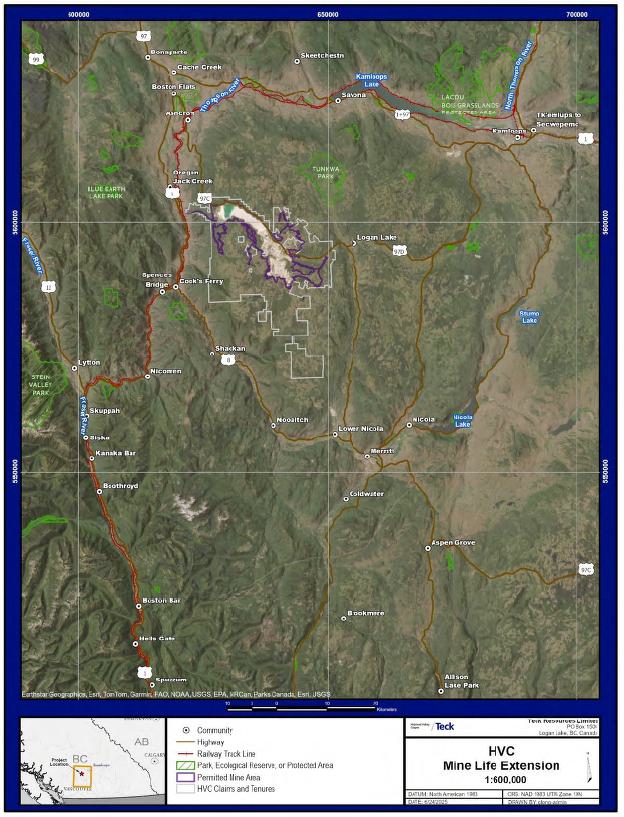
Figure 2-2: Project Location, Regional
Currency is expressed in Canadian dollars (C$) unless stated otherwise.
| October 2025 | Page 2- |
|
| NI 43-101 Technical Report on Highland Valley Copper Operations British Columbia |
| 2.3 | Qualified Persons |
This Report has been prepared by the following Qualified Persons (QPs):
| · | Mr. Christopher Hercun, P.Eng., Superintendent, Strategic Planning, Teck Highland Valley Copper Partnership; |
| · | Mr. Alex Stewart, P.Geo., Senior Mine Geostatistician, Strategic Planning, Teck Highland Valley Copper Partnership; |
| · | Mr. Tim Tsuji, P.Eng., Chief Mine Engineer, Strategic Planning, Teck Highland Valley Copper Partnership; |
| · | Mr. Frank Laroche, P.Eng., Principal Engineer Mineral Processing, Strategic Planning North America, Teck Resources Limited; |
| · | Mr. Carl Diederichs, P.Eng., Superintendent, Geotechnical, Teck Highland Valley Copper Partnership. |
| 2.4 | Site Visits and Scope of Personal Inspection |
| 2.4.1 | MR. CHRISTOPHER HERCUN |
Mr. Hercun has been a Teck employee since 2010 and has worked at the Highland Valley Copper Operations since 2013. While at the operations, he has routinely visited and inspected core drilling operations, core handling processes, the open pit workings, verified regulatory permitting, and visited key site infrastructure. He also participated in technical studies, planning, and economic evaluations related to the LOM plan and mine life extension studies.
| 2.4.2 | MR. ALEX STEWART |
Mr. Alex Stewart has been a Teck employee since 2011, working at the Highland Valley Copper operations throughout his tenure. He has been involved in Mineral Resource estimation since 2012. While on site he has visited and inspected the open pit workings, reviewed drilling operations, core logging, sampling procedures, shipping practices and core storage facility. He also reviewed and discussed geological interpretations and estimation practices with the geology group.
| 2.4.3 | MR. TIM TSUJI |
Mr. Tim Tsuji has been a Teck employee since 2012 and has worked at the Highland Valley Copper Operations as a long-term mine planner throughout his tenure. He has visited the open pit workings and revises their designs in response to changes in the resource models and economic, geotechnical, and operational conditions. He has been involved in Mineral Reserve and Mineral Resource estimation for the site since 2014.
| October 2025 | Page 2- |
|
| NI 43-101 Technical Report on Highland Valley Copper Operations British Columbia |
| 2.4.4 | MR. FRANK LAROCHE |
Mr. Laroche has been a Teck employee since 2008 and has worked at the Highland Valley Copper Operations for over 17 years. During his tenure, he has conducted site visits and inspected all of the current mineral processing stages, including the crushing, grinding, flotation, leaching and dewatering steps. He has provided contributions to geometallurgical programs through sample selection and performance analysis. He has direct involvement in copper recovery and throughput modeling, and familiar with the design and ongoing reconciliation process.
| 2.4.5 | MR. CARL DIEDERICHS |
Mr. Diederichs has been a Teck employee since 2008 and worked at the Highland Valley Copper Operations from 2008–2010, and from 2012 onward. While at the operations he has routinely visited and inspected the open pits, tailings, and waste rock storage facilities, and led, participated in, and reviewed their associated geotechnical studies. He has direct involvement in the planning and operation of the open pits, tailings and waste rock storage facilities and is familiar with their design and ongoing management practices.
| 2.5 | Effective Dates |
There are a number of effective dates pertinent to the Report, as follows:
| · | Date of the latest information on environmental, permitting, and social considerations: 18 June, 2025; |
| · | Date of the latest information on ongoing drill programs: 1 July, 2025; |
| · | Date of the close-out dates for Mineral Resource estimates: |
| o | Valley: 22 July, 2024; |
| o | Lornex: 22 June, 2024; |
| o | Highmont: 10 August, 2023; |
| o | Bethlehem: 31 March, 2016; |
| · | Effective date of the Mineral Resource estimates: 1 July, 2025; |
| · | Effective date of the Mineral Reserve estimates: 1 July, 2025. |
The overall Report effective date is taken to be 1 July, 2025, and is based on the effective date of the Mineral Reserve estimates.
| 2.6 | Information Sources and References |
The reports and documents listed in Section 27 of this Report were used to support Report preparation.
Additional information was sought from Teck personnel where required.
| October 2025 | Page 2- |
|
| NI 43-101 Technical Report on Highland Valley Copper Operations British Columbia |
| 2.7 | Previous Technical Reports |
Teck has previously filed the following technical reports on the Project:
| · | Graden, R., 2013: NI 43-101 Technical Report, Teck Highland Valley Copper, Highland Valley, British Columbia, Canada: report prepared for Teck Resources, effective date 6 March, 2013; |
| · | Graden, R., 2012: NI 43-101 Technical Report, Teck Highland Valley Copper, Highland Valley, British Columbia, Canada: report prepared for Teck Resources, effective date 1 March, 2012; |
| · | Graden, R., 2011: NI 43-101 Technical Report, Teck Highland Valley Copper, Highland Valley, British Columbia, Canada: report prepared for Teck Resources, effective date 8 April, 2011. |
| October 2025 | Page 2- |
|
| NI 43-101 Technical Report on Highland Valley Copper Operations British Columbia |
3 RELIANCE ON OTHER EXPERTS
This section is not relevant to this Report.
| October 2025 | Page 3- |
|
| NI 43-101 Technical Report on Highland Valley Copper Operations British Columbia |
4 PROPERTY DESCRIPTION AND LOCATION
| 4.1 | Introduction |
The Highland Valley Copper Operations are located approximately 75 km southwest of Kamloops British Columbia (BC) and 17 km west of the town of Logan Lake, BC. The centroid of the operations is situated at latitude 50° 28ʹ 27ʺ N and longitude 121° 01ʹ 15ʺ W.
| 4.2 | Ownership |
The operations are wholly-owned by Teck Resources Limited. Teck uses a subsidiary company, Teck Highland Valley Copper Partnership, as the operating entity.
| 4.3 | Mineral Tenure |
The mineral tenure area consists of 941 active mineral claims (55,625 ha), 106 active mining leases (3,391.1 ha) and 18 active Crown grants (private mineral holdings; 1,237.9 ha) that collectively cover about 60,254 ha. A complete list of the tenures, with their grant and expiry dates and areas, is provided in Appendix A. An overview map showing the tenure is provided in Figure 4-1. Detailed tenure maps are included in Appendix A.
All tenure is held 100% in the name of the Teck subsidiary Teck Highland Valley Copper Partnership.
The mineral claims and mining leases are renewed annually, per the BC Mineral Tenure Act. Crown grants are an interest in land as a fee simple estate in ownership. These rights are held in perpetuity by Highland Valley Copper Partnership if the assessed property and mineral taxes are paid annually. All required payments were current at the Report effective date.
| 4.4 | Surface Rights |
Surface rights in the Project general area are held by a number of different licence types (Table 4-1, Figure 4-2), all of which are 100% in the name of Teck Highland Valley Copper Partnership. A portion of the leases are land-based facility leases, which grant the holder the right to use the surface of the land for specific purposes outlined in the lease agreement.
Additional land acquisition may be required for easements to support the LOM plan. The following components may require additional land compared to the existing permitted area of operation:
| · | Relocation of Highway 97C north of the tailings storage facility (TSF); |
| · | Relocation of the transmission line north of the TSF; |
| · | Relocation of the gas line north of the Valley South waste rock storage facility (WRSF); |
| · | Relocation of the transmission line north of Valley South WRSF; |
| · | Relocation of Laura Lake Road. |
| October 2025 | Page 4- |
|
| NI 43-101 Technical Report on Highland Valley Copper Operations British Columbia |

Figure 4-1: Mineral Tenure Location Map
| October 2025 | Page 4- |
|
| NI 43-101 Technical Report on Highland Valley Copper Operations British Columbia |
Table 4-1: Surface Rights Table
| Tenure ID | Type | Status | Grant Date |
Expiry Date | Official Area (ha) |
| 0300010 | License of Occupation (BC) | Active | 5/27/2019 | N/A | — |
| LBF: 3400326, Lease No. 348211 | LBF-Lease (BC) | Active | 11/5/2006 | 11/5/2026 | 3.12 |
| LBF: 3400334, Lease No. 345796 | LBF-Lease (BC) | Active | 11/5/2011 | 11/5/2021; in renewal process |
3.40 |
| LBF: 3401427, Lease No. 338822 | LBF-Lease (BC) | Active | 6/15/2002 | 6/15/2032 | 0.02 |
| LBF: 3410895, Lease No. 340842 | LBF-Lease (BC) | Active | 4/29/2005 | 4/29/2035 | 0.04 |
| 001-892-673 | Fee simple (BC) | Active | 9/23/2009 | N/A | 20.43 |
| 003-840-573 | Fee simple (BC) | Active | 9/23/2009 | N/A | 0.33 |
| 004-027-663 | Fee simple (BC) | Active | 9/13/1892 | N/A | 90.66 |
| 004-027-779 | Fee simple (BC) | Active | 9/23/2009 | N/A | 8.18 |
| 004-027-795 | Fee simple (BC) | Active | 9/23/2009 | N/A | 3.67 |
| 004-027-817 | Fee simple (BC) | Active | 9/23/2009 | N/A | 12.59 |
| 004-474-902 | Fee simple (BC) | Active | 9/23/2009 | N/A | 60.26 |
| 004-474-953 | Fee simple (BC) | Active | 9/23/2009 | N/A | 4.78 |
| 004-475-127 | Fee simple (BC) | Active | 9/23/2009 | N/A | 0.30 |
| 004-475-241 | Fee simple (BC) | Active | 9/23/2009 | N/A | 0.42 |
| 004-475-259 | Fee simple (BC) | Active | 9/23/2009 | N/A | 4.10 |
| 004-475-267 | Fee simple (BC) | Active | 9/23/2009 | N/A | 1.10 |
| 004-509-781 | Fee simple (BC) | Active | 3/31/1970 | N/A | 20.89 |
| 004-509-846 | Fee simple (BC) | Active | 9/23/2009 | N/A | 16.76 |
| 004-509-927 | Fee simple (BC) | Active | 9/23/2009 | N/A | 19.00 |
| 004-510-020 | Fee simple (BC) | Active | 9/23/2009 | N/A | 17.55 |
| 004-510-089 | Fee simple (BC) | Active | 9/23/2009 | N/A | 21.14 |
| 004-510-135 | Fee simple (BC) | Active | 9/23/2009 | N/A | 20.90 |
| 004-510-518 | Fee simple (BC) | Active | 9/23/2009 | N/A | 19.66 |
| 004-510-585 | Fee simple (BC) | Active | 9/23/2009 | N/A | 18.86 |
| 004-512-138 | Fee simple (BC) | Active | 9/23/2009 | N/A | 19.11 |
| 004-512-383 | Fee simple (BC) | Active | 9/23/2009 | N/A | 18.76 |
| 004-512-413 | Fee simple (BC) | Active | 9/23/2009 | N/A | 17.40 |
| 004-512-464 | Fee simple (BC) | Active | 9/23/2009 | N/A | 20.49 |
| 004-512-529 | Fee simple (BC) | Active | 9/23/2009 | N/A | 18.35 |
| October 2025 | Page 4- |
|
| NI 43-101 Technical Report on Highland Valley Copper Operations British Columbia |
| Tenure ID | Type | Status | Grant Date |
Expiry Date | Official Area (ha) |
| 004-512-588 | Fee simple (BC) | Active | 9/23/2009 | N/A | 12.59 |
| 004-512-600 | Fee simple (BC) | Active | 9/23/2009 | N/A | 16.66 |
| 004-512-642 | Fee simple (BC) | Active | 9/23/2009 | N/A | 18.58 |
| 004-512-669 | Fee simple (BC) | Active | 9/23/2009 | N/A | 14.68 |
| 004-512-693 | Fee simple (BC) | Active | 9/23/2009 | N/A | 19.58 |
| 004-512-707 | Fee simple (BC) | Active | 9/23/2009 | N/A | 20.90 |
| 004-512-715 | Fee simple (BC) | Active | 9/23/2009 | N/A | 18.31 |
| 004-512-723 | Fee simple (BC) | Active | 9/23/2009 | N/A | 14.19 |
| 004-512-758 | Fee simple (BC) | Active | 9/23/2009 | N/A | 16.43 |
| 004-512-766 | Fee simple (BC) | Active | 9/23/2009 | N/A | 19.30 |
| 004-512-774 | Fee simple (BC) | Active | 9/23/2009 | N/A | 18.13 |
| 004-512-791 | Fee simple (BC) | Active | 9/23/2009 | N/A | 20.48 |
| 004-512-804 | Fee simple (BC) | Active | 9/23/2009 | N/A | 20.90 |
| 004-512-812 | Fee simple (BC) | Active | 9/23/2009 | N/A | 15.63 |
| 004-512-839 | Fee simple (BC) | Active | 9/23/2009 | N/A | 17.38 |
| 004-512-863 | Fee simple (BC) | Active | 9/23/2009 | N/A | 20.90 |
| 004-512-901 | Fee simple (BC) | Active | 9/23/2009 | N/A | 13.06 |
| 004-512-928 | Fee simple (BC) | Active | 9/23/2009 | N/A | 18.64 |
| 004-512-936 | Fee simple (BC) | Active | 9/23/2009 | N/A | 14.80 |
| 004-512-944 | Fee simple (BC) | Active | 9/23/2009 | N/A | 19.91 |
| 004-512-961 | Fee simple (BC) | Active | 9/23/2009 | N/A | 15.38 |
| 004-513-053 | Fee simple (BC) | Active | 9/23/2009 | N/A | 6.73 |
| 004-513-096 | Fee simple (BC) | Active | 9/23/2009 | N/A | 4.88 |
| 004-513-118 | Fee simple (BC) | Active | 9/23/2009 | N/A | 1.69 |
| 004-513-223 | Fee simple (BC) | Active | 9/23/2009 | N/A | 10.16 |
| 004-513-258 | Fee simple (BC) | Active | 9/23/2009 | N/A | 6.63 |
| 004-513-282 | Fee simple (BC) | Active | 9/23/2009 | N/A | 10.07 |
| 004-513-312 | Fee simple (BC) | Active | 9/23/2009 | N/A | 11.23 |
| 004-513-355 | Fee simple (BC) | Active | 9/23/2009 | N/A | 6.73 |
| 004-513-436 | Fee simple (BC) | Active | 9/23/2009 | N/A | 19.50 |
| 004-513-487 | Fee simple (BC) | Active | 9/23/2009 | N/A | 20.43 |
| 004-513-509 | Fee simple (BC) | Active | 9/23/2009 | N/A | 20.90 |
| 004-514-076 | Fee simple (BC) | Active | 9/23/2009 | N/A | 20.90 |
| 004-514-173 | Fee simple (BC) | Active | 9/23/2009 | N/A | 20.43 |
| 004-515-021 | Fee simple (BC) | Active | 9/23/2009 | N/A | 0.23 |
| 004-515-030 | Fee simple (BC) | Active | 9/23/2009 | N/A | 0.22 |
| October 2025 | Page 4- |
|
| NI 43-101 Technical Report on Highland Valley Copper Operations British Columbia |
| Tenure ID | Type | Status | Grant Date |
Expiry Date | Official Area (ha) |
| 004-515-048 | Fee simple (BC) | Active | 9/23/2009 | N/A | 0.59 |
| 004-515-064 | Fee simple (BC) | Active | 9/23/2009 | N/A | 104.84 |
| 004-515-170 | Fee simple (BC) | Active | 9/23/2009 | N/A | 3,675.36 |
| 004-516-087 | Fee simple (BC) | Active | 9/23/2009 | N/A | 28.77 |
| 004-516-991 | Fee simple (BC) | Active | 9/13/1892 | N/A | 65.77 |
| 005-028-418 | Fee simple (BC) | Active | 9/23/2009 | N/A | 0.16 |
| 005-028-442 | Fee simple (BC) | Active | 9/23/2009 | N/A | 0.19 |
| 005-028-451 | Fee simple (BC) | Active | 9/23/2009 | N/A | 0.31 |
| 005-151-988 | Fee simple (BC) | Active | 9/23/2009 | N/A | 226.37 |
| 005-151-996 | Fee simple (BC) | Active | 9/23/2009 | N/A | 210.99 |
| 008-972-150 | Fee simple (BC) | Active | 9/23/2009 | N/A | 0.18 |
| 014-189-208 | Fee simple (BC) | Active | 6/11/1968 | N/A | 783.88 |
Note. LBF lease = land-based facility lease; BC = British Columbia; N/A = not applicable.
| October 2025 | Page 4- |
|
| NI 43-101 Technical Report on Highland Valley Copper Operations British Columbia |
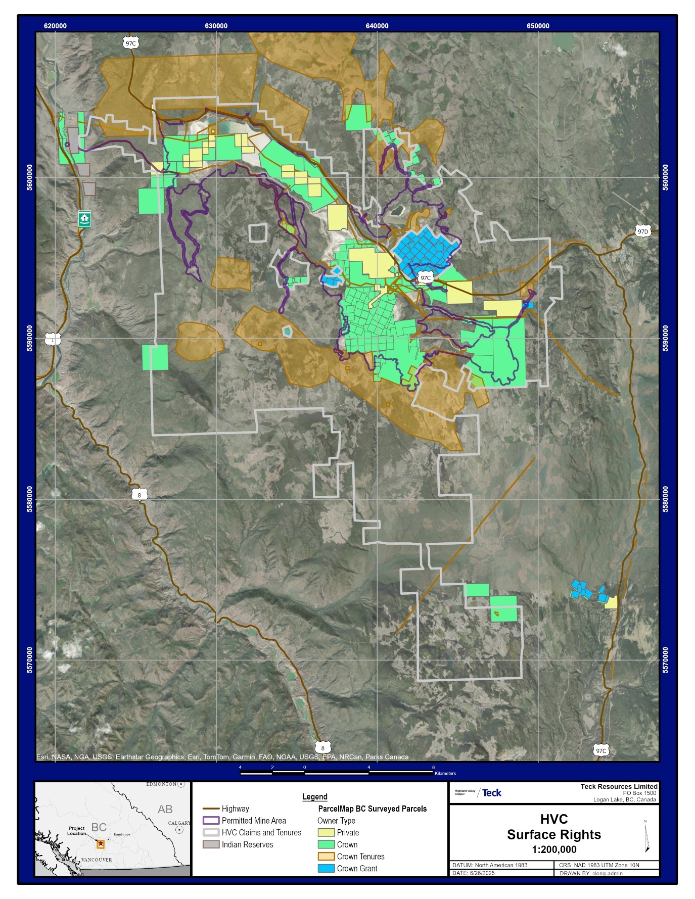
Figure 4-2: Surface Land Holders
| October 2025 | Page 4- |
|
| NI 43-101 Technical Report on Highland Valley Copper Operations British Columbia |
| 4.5 | Water Rights |
Teck currently holds 26 active BC water licences in the name of the Teck Highland Valley Copper Partnership, which have expiry dates ranging from 2026–2053 (Table 4-2). Water licences are renewed as necessary per the BC Water Sustainability Act.
| 4.6 | Royalties |
There are no royalties, back-in rights, payments or other agreements outside of the percentage distributions of the Teck Highland Valley Copper Partnership on claims held to cover the Highmont, Valley and Lornex open pits.
| 4.7 | Permitting Considerations |
Permitting for the Highland Valley Copper Operations is discussed in Section 20.
| 4.8 | Environmental Considerations |
Environmental considerations and monitoring programs for the Highland Valley Operations are discussed in Section 20.
There are environmental liabilities associated with the mining and processing activities. In order to minimize these environmental liabilities, Teck has secured all required environmental permits and conducts work in compliance with these permits. Additionally, Teck endeavors to comply with all applicable legal and other obligations.
| 4.9 | Social Considerations |
Social considerations for the Highland Valley Copper Operations are discussed in Section 20.
| 4.10 | QP Comment on Item 4 “Property Description and Location” |
To the extent known to the QPs, there are no other significant factors and risks that may affect access, title, or the right or ability to perform work on the Project that are not discussed in this Report.
| October 2025 | Page 4- |
|
| NI 43-101 Technical Report on Highland Valley Copper Operations British Columbia |
Table 4-2: BC Water Licences
| Licence ID | Grant Date | Expiry Date |
| 502087 | 12/17/2017 | 12/31/2028 |
| 503143 | 3/15/2021 | 12/31/2029 |
| 505227 | 10/12/2022 | 12/31/2053 |
| 505586 | 10/1/1972 | 12/31/2044 |
| C046527 | 6/17/1975 | 12/31/2026 |
| C046528 | 6/17/1975 | 12/31/2026 |
| C052985 | 5/24/1978 | 12/31/2026 |
| C052986 | 5/24/1978 | 12/31/2026 |
| C053704 | 4/6/1979 | 12/31/2026 |
| C058904 | 3/1/1979 | 12/31/2026 |
| C058905 | 3/1/1979 | 12/31/2026 |
| C059422 | 4/29/1980 | 12/31/2026 |
| C059470 | 11/22/1985 | 12/31/2026 |
| C061138 | 3/16/1983 | 12/31/2026 |
| C063018 | 10/15/1979 | 12/31/2026 |
| C063019 | 10/15/1979 | 12/31/2026 |
| C063020 | 8/13/1968 | 12/31/2026 |
| C114184 | 3/1/1999 | 12/31/2026 |
| C115461 | 6/13/1911 | 12/31/2026 |
| C118870 | 6/18/1984 | 12/31/2026 |
| C131299 | 8/22/1972 | 12/31/2026 |
| C131630 | 4/6/1979 | 12/31/2026 |
| C131662 | 6/18/1979 | 12/31/2026 |
| F007273 | 5/27/1921 | 12/31/2026 |
| F008111 | 1/31/1922 | 12/31/2026 |
| F048382 | 6/3/1968 | 12/31/2026 |
| 507170 | 11/7/2017 | 12/31/2027 |
| October 2025 | Page 4- |
|
| NI 43-101 Technical Report on Highland Valley Copper Operations British Columbia |
5 ACCESSIBILITY, CLIMATE, LOCAL RESOURCES, INFRASTRUCTURE AND PHYSIOGRAPHY
| 5.1 | Accessibility |
The operations are readily accessible by paved highway, including from Vancouver via Highway 1 to Highway 5 (the Coquihalla Highway) to Merritt, and then via Highway 97C to Logan Lake and the Highland Valley Copper Operations. Highway 97C also connects the site to Ashcroft, location of the railway terminal for copper concentrate handling.
No freight or passenger rail services are available directly from the site. The nearest freight rail services are at the Ashcroft terminal (access to both Canadian National (Canadian National) Railways and Canadian Pacific (Canadian Pacific) Railways with industrial transloading, materials handling, and industrial storage capabilities. Services offered at Ashcroft include bulk, break-bulk, and container (forthcoming) handling. Passenger rail services provided by VIA Rail and Canadian Pacific are available in Kamloops.
There are three airports within the Thompson–Nicola Regional District, one of which provides commercial services. The Kamloops Airport, serviced by Air Canada, West Jet, and Central Mountain Air, provides commercially scheduled and charter air transportation services for area residents and cargo to Vancouver, Calgary, and other western Canadian destinations. Non-commercial services are available at the Cache Creek/Ashcroft Airport and the Merritt Airport. The nearest international airport with commercial services is the Kelowna International Airport, located outside the Thompson–Nicola Regional District.
| 5.2 | Climate |
The climate is characterized as semi-arid, characterized by warm summers, cold winters, and the lack of a distinct wet season or dry season. Regional weather and climatic conditions are strongly influenced by elevation, slope aspect and proximity to Kamloops Lake and the Thompson River valley. Temperatures range from an average daily maximum of 21.2°C in the summer to an average daily minimum of -9.7°C in the winter. Extreme temperatures have reached a low of -43.9°C and a high of 35.0°C.
The mine site experiences a rain-shadow effect from the Pacific Coastal Mountains that are situated to the west. Precipitation occurs as both rain and snow, with a higher contribution from rainfall on an average annual basis. The Highland Valley area receives an average of 393 mm of precipitation annually, of which about 243 mm falls as rain. Convective storms are an important source of precipitation in the summer and average precipitation is generally highest in June. Winter precipitation in the form of snow is relatively low and accumulation varies with topography and elevation; snowfall is generally highest in December. Snow melt typically occurs in mid-April, initiating freshet.
Valley bottoms are arid, with potential evaporation substantially higher than precipitation.
The prevailing wind direction in the Highland Valley is from west to east, particularly in the summer months.
Mining operations are conducted year-round.
| October 2025 | Page 5- |
|
| NI 43-101 Technical Report on Highland Valley Copper Operations British Columbia |
| 5.3 | Local Resources and Infrastructure |
Infrastructure that supports the current operations is in place (see also discussions in Section 16, Section 17, and Section 18 of this Report). These Report sections also discuss water sources, electricity, personnel, and supplies for the LOM plan.
The nearest communities to the mining operation are Logan Lake (17 km), Ashcroft/Cache Creek (34 km), Merritt (60 km), and Kamloops (75 km).
| 5.4 | Physiography and Land Use |
The mine is located within the approximately 23 km long Highland Valley, at the lower elevation end of the Thompson Plateau in the southern Interior Plateau region of BC, on the eastern slope of the Pacific Coastal Mountains.
Multiple glaciations and subsequent erosion and deposition of post-glacial streams shaped the Highland Valley, and bedrock structural features mainly control its topography. Glacial and post-glacial deposits cover more than 90% of the bedrock. The western part of the Highland Valley exhibits distinct hanging valley features, while the axis of its eastern part narrows into a bedrock canyon.
The Highland Valley is bounded on the west by the Thompson River, and on the east by the Guichon Creek Valley.
The region is characterized as having hummocky terrain with gentle (5%) to moderate (50%) slopes. The elevation in the valley ranges from 1,000–1,850 metres above sea level (masl). The Project area ranges in elevation from 1,000–1,750 masl with the highest elevations occurring in the southwestern part of the area. The mining operations are situated at approximately 1,280 masl.
The mining operations are within the Thompson Basin and Guichon Upland Ecosections of the Thompson–Okanagan Plateau Ecoregion. Species vary depending on moisture availability, elevation, and aspect, and typically consist of fire-dominated, dry-land vegetation. Key species in the Project area include:
| · | Big sagebrush, common rabbit brush, and bluebunch wheatgrass communities, with scant forest cover, occurring in valley bottoms at around 250 m in elevation up to 800 m on southern aspects; |
| · | Ponderosa pine and Douglas fir communities, occurring from about 500–1,050 m on south aspects; |
| · | Douglas fir, ponderosa pine, hybrid white spruce, paper birch and black cottonwood communities, occurring from approximately 1,300–1,600 m in elevation; |
| · | Engelmann spruce, subalpine fir and lodgepole pine communities, occurring from about 1,600–2,050 m in elevation. |
Changes to vegetation and ecosystems in the Highland Valley have occurred over time because of both natural (e.g., forest succession, fires, climate change) and anthropogenic (e.g., agriculture, forestry, mining, recreational development) forces and activities.
| October 2025 | Page 5- |
|
| NI 43-101 Technical Report on Highland Valley Copper Operations British Columbia |
The Project area is included in the General Resource Management Zone defined under the Kamloops Land and Resource Management Plan, within which mineral development is identified as an allowable land use. The Kamloops Land and Resource Management Plan outlines objectives and strategies for mineral development that provides for local employment and investment, and for maintaining or enhancing land access for mineral exploration and development. The Kamloops Land and Resource Management Plan specifically identifies Highland Valley Copper as a large, producing metal mine in the region.
The Thompson–Nicola Regional District has a history of development and land use that includes forestry, ranching, and mining dating back to the early 1900s. It currently supports substantial urban settlement, mining, forestry, agriculture, recreation, and transportation including several highway and railway corridors.
The lands surrounding the operations primarily consist of forest and grassland ecosystems, which are used by Indigenous peoples for economic, cultural, and spiritual purposes. In addition, the region supports various land uses such as parks and protected areas, recreational activities such as trails, hunting, and fishing, as well as forestry and agricultural practices, including ranching and rangeland.
There are no provincially designated parks or protected areas within, or overlapping, the mine site, although there are seven provincial parks within 25 km of the operations.
The mine site is located within the Kamloops timber supply area and overlaps 40 active or pending cut blocks. Teck holds 31 of these, and nine intersect with forest licenses held by private entities.
The operations are surrounded by cattle ranching, with five crown land range tenures adjacent to the mine.
The Highland Valley is a significant area for Indigenous Peoples who have historically occupied the area and continue to use it today; primary and traditional uses include but are not limited to: hunting, fishing, gathering, other cultural and spiritual purposes, agriculture, and livestock watering. The Highland Valley Copper Operations are located within the unceded territory of the Nlaka’pamux Nation, and the Secwépemc Nation also have interests in the area.
| 5.5 | Seismicity |
Seismic assessments suggest that seismic hazards for the operations can come from three sources, shallow crustal earthquakes, great subduction-interface earthquakes, and deep in-slab earthquakes. The local crustal earthquakes are the most likely in southern BC.
A deterministic seismic hazard assessment completed in 2018 indicated low predicted peak ground accelerations in the vicinity of the main mine infrastructure.
| 5.6 | Sufficiency of Surface Rights |
Surface rights for the current operations are in place.
Additional land acquisition for easements may be required to support the LOM plan (see Section 4.4).
| October 2025 | Page 5- |
|
| NI 43-101 Technical Report on Highland Valley Copper Operations British Columbia |
6 HISTORY
| 6.1 | Ownership, Exploration, and Development History |
The exploration and development history is outlined in Table 6-1.
Mining began in 1962 at the Bethlehem Copper operation. Three open pits (Huestis, Jersey, and Iona) and two TSFs, the Bethlehem and Trojan TSFs, were developed during the Bethlehem Copper operation and were used until 1982. In 2019, Teck received an amendment to the M-11 Mines Act permit to allow for additional mining from the Jersey and Iona pits, but as of the Report effective date, none of the Huestis, Jersey, and Iona pits or the Bethlehem and Trojan TSFs were active.
In 1972, the Lornex Mining Corporation started production, developing the Lornex open pit and constructing the Highland mill and TSF, all of which continue at the Report effective date.
Highmont Mining Corporation operated from 1980–1984, developing the Highmont East pit, the Highmont West pit, the Highmont mill and the Highmont TSF. Mining recommenced in 2005 from the Highmont East pit, and re-purposed the Highmont West pit as a WRSF. The Highmont TSF is inactive at the Report effective date.
Cominco (now Teck) acquired Bethlehem Copper in 1980 to consolidate its holdings in the area, which were centered on the Valley deposit, and started production from the Valley pit in 1983. The Bethlehem mill processed ore from the Valley pit until 1986, when the Highland Valley Copper Partnership was formed between Cominco and Lornex, and the Highland (Lornex) mill began processing Valley ore. In 1987, Highmont was added to the Highland Valley Copper Partnership and in 1989 the Highmont mill was moved to its current location, adjacent to the Highland mill. In 2014, the Highland Valley Copper Partnership completed a large mill optimization program centred around a new, modern flotation complex.
In 2018, Teck formally began permitting activities for the Highland Valley Copper Operations mine life extension with the Province of British Columbia, to extend operations to 2040 or beyond by mining additional material from the Highmont and Valley pits and increasing the capacity of the Highland TSF. The permit was granted on 17 June, 2025 (see Section 20.1).
The locations of the current and former open pits are provided in Figure 6-1.
| 6.2 | Production History |
The production history is provided in Table 6-2. Reliable production information is not available prior to the Highland Valley Copper Partnership merger in 1986; thus the table only provides verifiable production data from 1986 onwards.
| October 2025 | Page 6- |
|
| NI 43-101 Technical Report on Highland Valley Copper Operations British Columbia |
Table 6-1: Ownership, Exploration and Development History
| Year | Operator | Work Conducted |
| 1899 | Early prospecting activities. Claims staked in the area now known as the Snowstorm zone. | |
| 1907–1920s | The first mining in the Guichon Creek batholith started around 1907 when a wagon trail was built to Ashcroft and hand-sorted copper ore was sent to a smelter in Trail from the Snowstorm and Iona Zones of the Bethlehem deposit. Exploration and mining in the area continued through to the 1920s. | |
| 1950s | Egil Lorentzen | Staked the ground over the Lornex deposit. |
| Various prospectors | Staked claims over the Highmont deposit. | |
| 1954 | Huestis–Reynolds Syndicate | Prospected in the Highland Valley and staked about 100 mineral claims covering the Snowstorm, Iona, and Jersey zones. |
| 1955 | Bethlehem Copper Corporation, Ltd. (Bethlehem Copper) | Company incorporated, purchased the Huestis-Reynolds Syndicate claims. |
| 1955–1958 | American Smelting and Refining Co. (Asarco) | Optioned property. Completed geophysical surveying, trenching and core drilling. |
| 1957 | Kenneco Exploration | Completed out the first induced polarization (IP) survey on the ground overlain by the Valley deposit in 1957. The chargeability anomalies were weak and did not match the exploration model being used, so the property was dropped. |
| 1959–1960 | Bethlehem Copper | Conducted an underground program to check the results of Asarco's core drilling. A participation and financing agreement was negotiated with Sumitomo Metal Mining Co. of Japan in 1960 to build a 3,000 ton/day mill and to put the East Jersey zone into production. |
| 1961 | Huestis Mining Company | Consolidated claims held by three other mining companies, B.X. Mining Company Ltd., Buttle Lake Mining Company Ltd., and Northwest Ventures Ltd. |
| 1962–1965 | Bethlehem Copper | Mining of initial phase of Jersey open pit at 3,000 t/d. |
| 1963 | Cominco Ltd. | Staked claims adjoining the Huestis holdings. |
| 1964 | Egil Lorentzen | Malachite staining identified, minor trenching. |
| 1964–1982 | Bethlehem Copper | Second phase of mining of Jersey open pit at 15,000 t/d. |
| 1965 | Egil Lorentzen | Formed the Lornex Mining Company and entered into an option agreement with Rio Tinto Canadian Exploration (Rio Tinto) and its partner Yukon Consolidated Gold Corporation (Yukon Consolidated). |
| 1966 | Highmont Mining Corp. Ltd. | Company formed. |
| 1966–1972 | Rio Tinto, Yukon Consolidated, Lornex Mining Company |
Through funding exploration work for shares in Lornex Mining Company, Rio Tinto earned a 60% interest in the property and control of the company. Yukon Consolidated earned an interest in the property through its agreement with Rio Tinto to fund 40% of Rio Tinto’s work in the province of British Columbia. An IP survey led the company to conclude that the deposit anomaly extended on adjacent ground held at the time by Skeena Silver Mines Ltd (Skeena). An option agreement with Skeena led to the drill program that outlined the Lornex copper zone. Stripping of the Lornex deposit commenced 1970, and mining began in 1972. |
| October 2025 | Page 6- |
|
| NI 43-101 Technical Report on Highland Valley Copper Operations British Columbia |
| Year | Operator | Work Conducted |
| 1967 | Cominco Ltd. (Cominco) | IP survey revealed two broad anomalies, the A zone (Bethsaida) and the B zone (Valley). Drilling encountered significant copper mineralization, but the anomaly extended onto adjacent claims held by Bethlehem Copper. The two companies traded claims, where the Cominco subsidiary Valley Copper Mines received the claims that overlaid the B zone and Bethlehem Copper received claims for tailings storage. Additional drilling showed that 20% of the mineralization was still overlain by claims held by Bethlehem Copper. |
| 1969–1982 | Teck Corporation Ltd. | Took over exploration activities from Cominco, and, after detailed feasibility studies in 1971 and 1978, put the Highmont mine into production in 1980. Production halted in 1984 due to low metal prices. |
| 1970–1976 | Bethlehem Copper | Mining of Huestis open pit. |
| 1976–1979 | Bethlehem Copper | Mining of Iona open pit. |
| 1981 | Cominco | Purchased 100% ownership of Valley Copper Mines and Bethlehem Copper. |
| 1982 | Cominco | Closure of Bethlehem mine. |
| 1983 | Cominco | Start of mining of the Valley deposit, with ore processed at the Bethlehem mill. |
| 1986 | Cominco | Formation of the Highland Valley Copper Partnership between Cominco Ltd. (55%) and Lornex Mining Co. (45%). Valley ore processed at the Highland (Lornex) mill. |
| 1988 | Highland Valley Copper Partnership | An agreement was concluded to bring the Highmont mine and mill into the Highland Valley Copper partnership. Ownership became Cominco Ltd. 50%; Rio Algom Ltd. 33.6%; Teck Corporation 13.9% and Highmont Mining Ltd. 2.5%. |
| 1989 | Highland Valley Copper Partnership | Highmont mill moved to a site adjacent to the Highland mill. The Bethlehem mill was closed. |
| 2000 | Billiton plc (Billiton) | Purchased Rio Algom Limited. |
| 2001 | Teck Cominco Limited | Merger between Cominco Limited and Teck Corporation, consolidating their stakes in the Highland Valley Copper Partnership. Ownership became Teck Cominco Ltd. 63.9%; Billiton 33.6%; and Highmont Mining Ltd. 2.5%. |
| 2002 | BHP Billiton plc | Merger between BHP Ltd and Billiton. |
| 2004 | Teck Cominco | Acquired BHP Billiton’s interest in the Highland Valley Copper Partnership, giving Teck Cominco a 97.5% interest. |
| 2005 | Teck Cominco | Production from the Highmont East pit was resumed. |
| 2009 | Teck | Teck Cominco Limited changed its name to Teck Resources Limited. |
| 2016 | Teck | Purchased remaining 2.5% interest in Highland Valley Copper Partnership from Highmont Mining Ltd. |
| 2017 | Teck | Completed construction of mill optimization project, increasing mill throughput and recovery. |
| 2020 | Teck | Completed construction of D3 ball mill, the 14th grinding mill in the mill complex. |
| 2025 | Teck | Environmental Assessment Certificate received for HVC Mine Life Extension project, allowing extension of Valley and Highmont pits, associated WRSFs and Highland TSF to extend mine life to 2046. |
| October 2025 | Page 6- |
|
| NI 43-101 Technical Report on Highland Valley Copper Operations British Columbia |
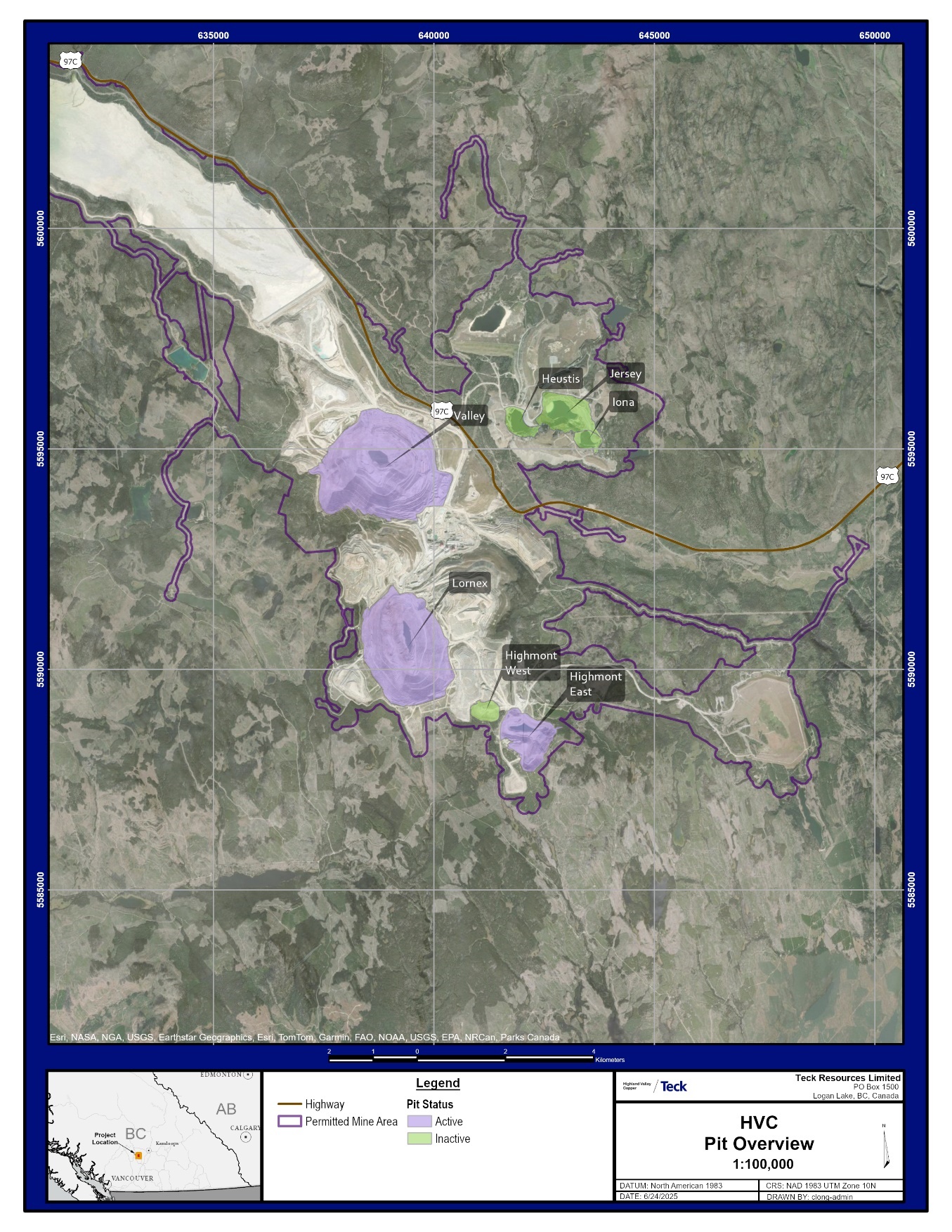
Figure 6-1: Location Plan, Current and Former Open Pits
| October 2025 | Page 6- |
|
| NI 43-101 Technical Report on Highland Valley Copper Operations British Columbia |
Table 6-2: Production Table
| Year | Copper (kt) |
Molybdenum (kt) |
Year | Copper (kt) |
Molybdenum (kt) |
| Pre-1986 | n/a | n/a | 2005 | 173 | 2.9 |
| 1986 | 71 | 2.0 | 2006 | 166 | 1.9 |
| 1987 | 157 | 2.8 | 2007 | 135 | 1.8 |
| 1988 | 170 | 1.9 | 2008 | 115 | 1.9 |
| 1989 | 113 | 1.4 | 2009 | 114 | 3.0 |
| 1990 | 164 | 1.9 | 2010 | 95 | 3.1 |
| 1991 | 172 | 1.7 | 2011 | 94 | 3.6 |
| 1992 | 171 | 1.8 | 2012 | 113 | 4.5 |
| 1993 | 157 | 1.7 | 2013 | 110 | 2.8 |
| 1994 | 161 | 1.6 | 2014 | 118 | 2.3 |
| 1995 | 158 | 1.6 | 2015 | 147 | 1.5 |
| 1996 | 149 | 1.3 | 2016 | 115 | 2.5 |
| 1997 | 157 | 2.0 | 2017 | 90 | 4.2 |
| 1998 | 167 | 2.4 | 2018 | 97 | 4.0 |
| 1999 | 106 | 1.4 | 2019 | 117 | 3.0 |
| 2000 | 184 | 2.0 | 2020 | 115 | 1.5 |
| 2001 | 181 | 1.9 | 2021 | 127 | 0.5 |
| 2002 | 175 | 2.5 | 2022 | 115 | 0.4 |
| 2003 | 165 | 3.4 | 2023 | 96 | 0.6 |
| 2004 | 165 | 4.9 | 2024 | 99 | 0.9 |
| 2025 | 62 | 0.7 |
Note: n/a = not applicable. No reliable production data is available prior to 1986. 2025 production data is a partial year, from 1 January 2025 to 30 June, 2025.
| October 2025 | Page 6- |
|
| NI 43-101 Technical Report on Highland Valley Copper Operations British Columbia |
7 GEOLOGICAL SETTING AND MINERALIZATION
| 7.1 | Regional Geology |
The Project is situated within the allochthonous Quesnel Island Arc Terrane of the southeastern Intermontane Belt. Intrusions belonging to the Lower Jurassic Guichon Suite are a major component of the Quesnel terrane, extending over a surface area of more than 1,000 km2. Plutonism migrated from west to east during the formation of the upper Triassic to lower Jurassic Nicola Group, with the Guichon Creek Batholith representing the oldest (~210 Ma), and westernmost intrusion belt of the Quesnel terrane.
The intrusive rocks are spatially related to the volcano–sedimentary units of the Nicola Group. Major lithologies within the Nicola Group include calc-alkaline andesite, dacite, and rhyolite flows and ignimbrites, with relatively alkaline augite porphyry flows, analcite trachybasalt and trachyandesites, and minor limestones, shale, and quartzite.
Rapid uplift and erosion of the batholith resulted in formation of Jurassic sedimentary basins along the north and northwest margins of the batholith. Rocks of the basin-fill Ashcroft Formation consist of argillite, siltstone, sandstone, conglomerate, and minor limestone. Overlying the Jurassic rocks along the southwest flank of the batholith are mid-Cretaceous volcanic units of the Spences Bridge Group comprising mafic to felsic lavas, and volcaniclastic and interbedded epiclastic rocks. Tertiary continental volcanic and sediments cover extensive areas of the batholith, overlying earlier units from north of Highland Valley to the Thompson River.
Recent glacial-derived deposits overlie all lithologies.
A regional geology plan is included as Figure 7-1.
| 7.2 | Project Geology |
| 7.2.1 | LITHOLOGIES |
In the vicinity of the Guichon Creek Batholith in the Highland Valley, the Nicola Group is primarily volcanic in composition on the northern and eastern rim of the batholith, consisting of basalts and basaltic andesites, with locally abundant breccias and agglomerates. Sedimentary rocks are more common on the southern and western batholith margins, and comprise chert, siltstone, sandstone, greywacke, limestone, and volcanic conglomerate which grades to sedimentary volcanic breccia.
The Guichon Creek Batholith extends over an approximate area of 60 x 30 km. It is a is a north–northwest elongated multi-phase intrusion with major compositional variations that evolve from an older mafic margin inward to a younger and generally more felsic core (Table 7-1).
Contacts between the phases, though locally sharp, are commonly gradational and define an annular zoning with the older phases towards the outer margins of the batholith and the younger phases within the central area. The phases are nearly concentric in plan view.
| October 2025 | Page 7- |
|
|
NI 43-101 Technical Report on Highland Valley Copper Operations British Columbia |
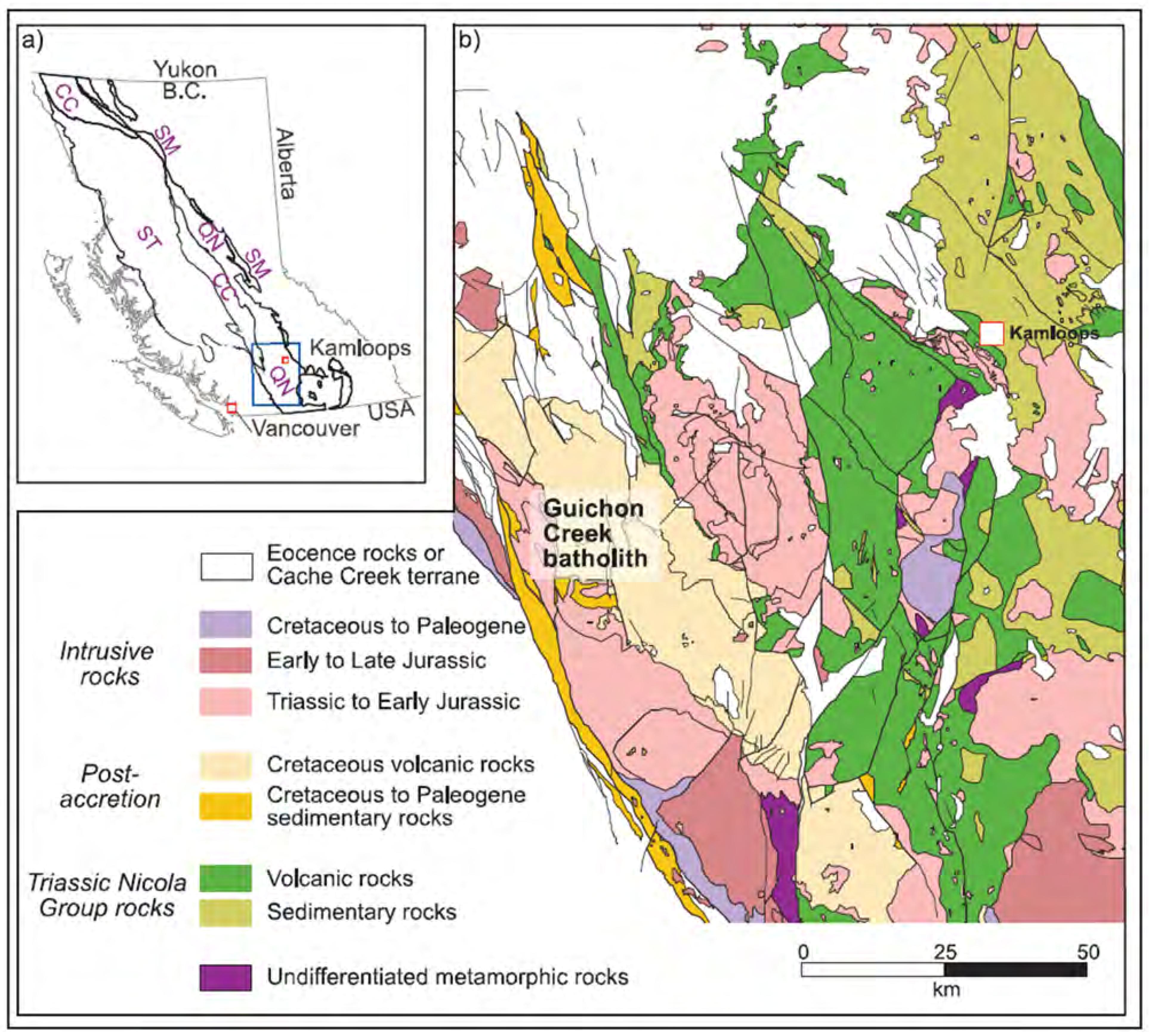
Note: Figure from Ryan et al., (2020). CC: Cache Creek ; QN: Quesnel; ST: Stikine; SM: Slide Mountain.
Figure 7-1: Regional Geology Map
| October 2025 | Page 7- |
|
|
NI 43-101 Technical Report on Highland Valley Copper Operations British Columbia |
Table 7-1: Key Phases, Guichon Creek Batholith
| Lithology/Facies | Sub-facies/Phase | Description |
| Border | Melanocratic, medium-grained diorite to gabbro-diorite). Mafic-enriched amphibole, biotite, and local pyroxene as cores in amphiboles, commonly displays strong seriate texture. Approx 50% hornblende and biotite. | |
| Highland Valley | Guichon granodiorite | Quartz diorite to granodiorite, medium-grained, equigranular to seriate texture. Hornblende predominates and the facies is distinguished by conspicuous primary K-feldspar. 25% hornblende and biotite. |
| Chataway granodiorite | Granodiorite, hypidiomorphic granular and seriate texture. Abundances of biotite and hornblende are routinely equal. Anhedral quartz grains, and unevenly distributed clusters of hornblende and biotite (20%). | |
| Bethlehem | Bethlehem granodiorite | Medium-grained inequigranular but grades into plagioclase and quartz-phyric phanerocrystalline facies. Distinguished by 1 cm poikilitic hornblende and locally coarse poikilitic potassic feldspar in groundmass of evenly distributed fine- to medium-grained mafic minerals. Quartz is ameboid. 15% hornblende and biotite. |
| Skeena granodiorite | Contact zone of Bethlehem granodiorite and Bethsaida granodiorite, similar in texture to Bethlehem but grain size is larger, mafic content is lower, and quartz is coarse-grained and subhedral to anhedral. Biotite is subhedral to euhedral and hornblende Is Irregular, anhedral, and commonly poikilitic. <10% hornblende and biotite. | |
| Bethsaida | Bethsaida granodiorite to quartz monzonite | Varies from granodiorite to quartz monzonite. Medium- to coarse-grained with coarse phenocrysts of quartz and biotite, average 0.5–1.0 cm. Distinct, euhedral biotite books (approx. 1 cm). 1% accessory minerals of hornblende, magnetite, hematite, sphene, apatite, and zircon. 6% biotite. |
| Salt and pepper granodiorite | Slightly porphyritic and medium-grained, plagioclase displays oscillatory zoning, quartz anhedral interstitial grain aggregates, orthoclase is interstitial and perthitic. Distinct, approximately 3–15% (but average >12%) disseminated 1 mm biotite and magnetite crystals. | |
| Feldspar-phyric inequigranular granodiorite | Medium- to coarse-grained plagioclase and quartz phenocrysts. Mafic (biotite) phenocrysts average <0.3 cm and <2%. Trace magnetite and hematite. Similar to salt and pepper facies, but with distinct feldspar phenocrysts (0.5 cm average) and sparse biotite. | |
| Biotite- and magnetite-rich cumulate | Mafic-cumulate facies with 25–60%euhedral, coarse-grained biotite (0.5 cm average). Locally 5–30% fine-grained disseminated magnetite clusters and veins. Commonly associated with stronger K-feldspar alteration. |
| October 2025 | Page 7- |
|
|
NI 43-101 Technical Report on Highland Valley Copper Operations British Columbia |
Numerous syn- to post-mineralization porphyritic to aplitic dykes and stocks cut the main intrusive facies with the highest density occurring primarily within and adjacent to the porphyry deposits. The most significant of the dykes are the northwesterly-striking Gnawed Mountain dyke that is associated with mineralization at the Highmont deposit, and a northerly-striking dyke swarm that extends from the Skuhun Creek fault through the Highland Valley to the Barnes Creek fault.
The porphyry deposits are hosted either in younger phase rocks, or in dyke swarms and intrusive breccias associated with the younger phase rocks.
A project-wide geology map is provided in Figure 7-2.
| 7.2.2 | STRUCTURE |
The batholith is elongated northward and segmented by major north- and northwest–west-striking faults that are closely related to mineralization (refer to Figure 7-2). The major northerly-trending structures include the central Lornex fault, the bounding Guichon Creek fault to the east, and the Western Boundary Fault to the west. Northwesterly-trending structures include the Skuhun Creek, Highland Valley, and Barnes Creek faults.
Dykes appear to preferentially occupy large-scale tension fractures that have similar orientations to the major fault directions.
| 7.2.3 | METAMORPHISM AND ALTERATION |
Adjacent to the batholith contact, a metamorphic halo up to 500 m wide developed. Close to the batholith contact, assemblages are typical of the hornblende hornfels facies, further out, albite–epidote facies are typical.
Hydrothermal alteration of the Highland Valley deposits was generated by multiple generations of magmatic-hydrothermal fluid originating with the causative intrusion at depth.
Distal alteration includes green sericite, epidote, and chlorite, as veins and as fracture coatings. The type of vein alteration developed can reflect host rock composition; green sericite veins characterise the more felsic Bethlehem, Skeena, and Bethsaida phases, but chlorite (epidote) veins are more common in the earlier, more mafic batholith phases. Moderately to strongly developed distal alteration zones surround each of the five main deposits.
Proximal alteration and veining types include a barren core of intense quartz veining, potassic (potassic feldspar and hydrothermal biotite) and muscovite dominant. These are overprinted by late, structurally controlled sericitic and argillic alteration.
| 7.2.4 | MINERALIZATION |
The major deposits are in the centre of the batholith, and include the Valley, Lornex, Highmont, Bethlehem, and JA deposits (refer to Figure 7-2). All the deposits except the JA deposit have been or are being mined; JA remains undeveloped.
| October 2025 | Page 7- |
|
|
NI 43-101 Technical Report on Highland Valley Copper Operations British Columbia |

Note: Figure from Ryan et al., (2020).
Figure 7-2: Deposit Area Geology Plan
| October 2025 | Page 7- |
|
|
NI 43-101 Technical Report on Highland Valley Copper Operations British Columbia |
Significant copper mineralization occurred in several stages. The oldest followed the emplacement of Bethlehem granodiorite subfaces and coincided with dyke intrusion and breccia formation in the Bethlehem area; Bethlehem (and possibly the JA) is dated ca 209 Ma. The second phase, dated at ca 208 Ma, followed emplacement of the Skeena sub-facies and Bethsaida granodiorite sub-facies. The Valley, Lornex, Highmont systems formed at this time.
Most of the sulphide mineralization is developed in fractures, veins, faults, or breccia bodies. Higher grades typically occur where the fracture density is high or where several sets of fracture swarms overlap.
The first copper-mineralizing event followed the formation of the Bethlehem facies and occurred with the emplacement of porphyry dykes and breccias into these facies, forming the Bethlehem deposit. The second, and larger, copper–molybdenum mineralizing event followed the emplacement of the Bethsaida facies and resulted in the formation of the Valley–Lornex and Highmont deposits.
The originally contiguous Valley–Lornex deposit was cut by the late-stage Lornex fault, offsetting the Valley and Lornex deposits by about 3.5 km.
| 7.3 | Deposit Descriptions |
| 7.3.1 | VALLEY DEPOSIT |
7.3.1.1 Deposit Dimensions
Chalcopyrite mineralization at the Valley deposit has a footprint of 2 x 1.5 km, which is elongate to the northwest. The deposit remains open at depth and has been drill tested to approximately 1,200 m depth.
7.3.1.2 Lithologies
The major lithologies are summarized in Table 7-2. A geology plan is provided in Figure 7-3, and an example cross-section in Figure 7-4.
Mineralization is hosted within the Bethsaida and Skeena phases of the Guichon Creek Batholith. The gradational northeast-dipping contact between these phases is preserved in the Lornex pit. In the Valley pit, this contact occurs to the north of the deposit. This difference in the location of the Bethsaida/Skeena contact relative to the mineralization in the Lornex and Valley pits is interpreted to be the result of a deeper level of erosion in the Valley area.
7.3.1.3 Structure
Three major fault systems cut the Valley–Lornex deposit (Table 7-3 and refer to Figure 7-3):
| • | Lornex fault; |
| • | Yellow fault system; |
| • | Highland Valley fault system. |
| October 2025 | Page 7- |
|
|
NI 43-101 Technical Report on Highland Valley Copper Operations British Columbia |
Table 7-2: Key Lithologies, Valley–Lornex Deposit
| Lithology | Phase | Description |
| Lamprophyre dykes | Post-mineral |
Consist of spessartites, and hornblende vogesites. Cut porphyry-related alteration and mineralization and often exhibit weak iron carbonate alteration along their contacts. |
| Quartz–feldspar porphyry 2 (QFP2); tan porphyry (TP) | Syn-mineral | Euhedral, porphyritic quartz and plagioclase phenocrysts hosted within an aphanitic groundmass. Typically, 0.5-5 m in width. |
| Bethsaida porphyry (BP); quartz eye aplite (Apl-Q) and aplite/fine-grained granite (Apl-Gr) | Syn-mineral | Euhedral, porphyritic quartz and lesser plagioclase phenocrysts hosted within an aplitic groundmass. Typically, 0.5-5 m in width. Often coincident with mineralization and barren high-temperature veining. |
| Bethsaida salt-and-pepper porphyry (BSP) | Early mineral |
Typically inequigranular, with fine-grained biotite ± magnetite and oscillatory-zoned plagioclase phenocrysts associated with anhedral quartz ‘eyes’ ranging from 3–15 mm in size. Three north–northwest-trending elongated stocks of the salt-and-pepper porphyry occur within the central and southeast domains of the Valley deposit. |
| Quartz–feldspar porphyry (QFP) | Early mineral | Euhedral, porphyritic quartz and plagioclase phenocrysts and aphanitic to saccharoidal groundmass. Dykes are typically steeply northeast- and southwest-dipping, narrow (1–30 m thick), planar intrusive bodies with sharp to gradational (often chilled) contacts with Bethsaida phase granodiorite. |
| Guichon Creek Batholith (GCB) | Pre-mineralization | Weakly porphyritic granodiorite and monzogranite. Contacts between Bethsaida and Skeena facies are geochemically and visually gradational over several meters and occur to the northwest of the Valley pit. Additional intrusive dyke phases range from pre- to syn-mineral. |
| October 2025 | Page 7- |
|
|
NI 43-101 Technical Report on Highland Valley Copper Operations British Columbia |
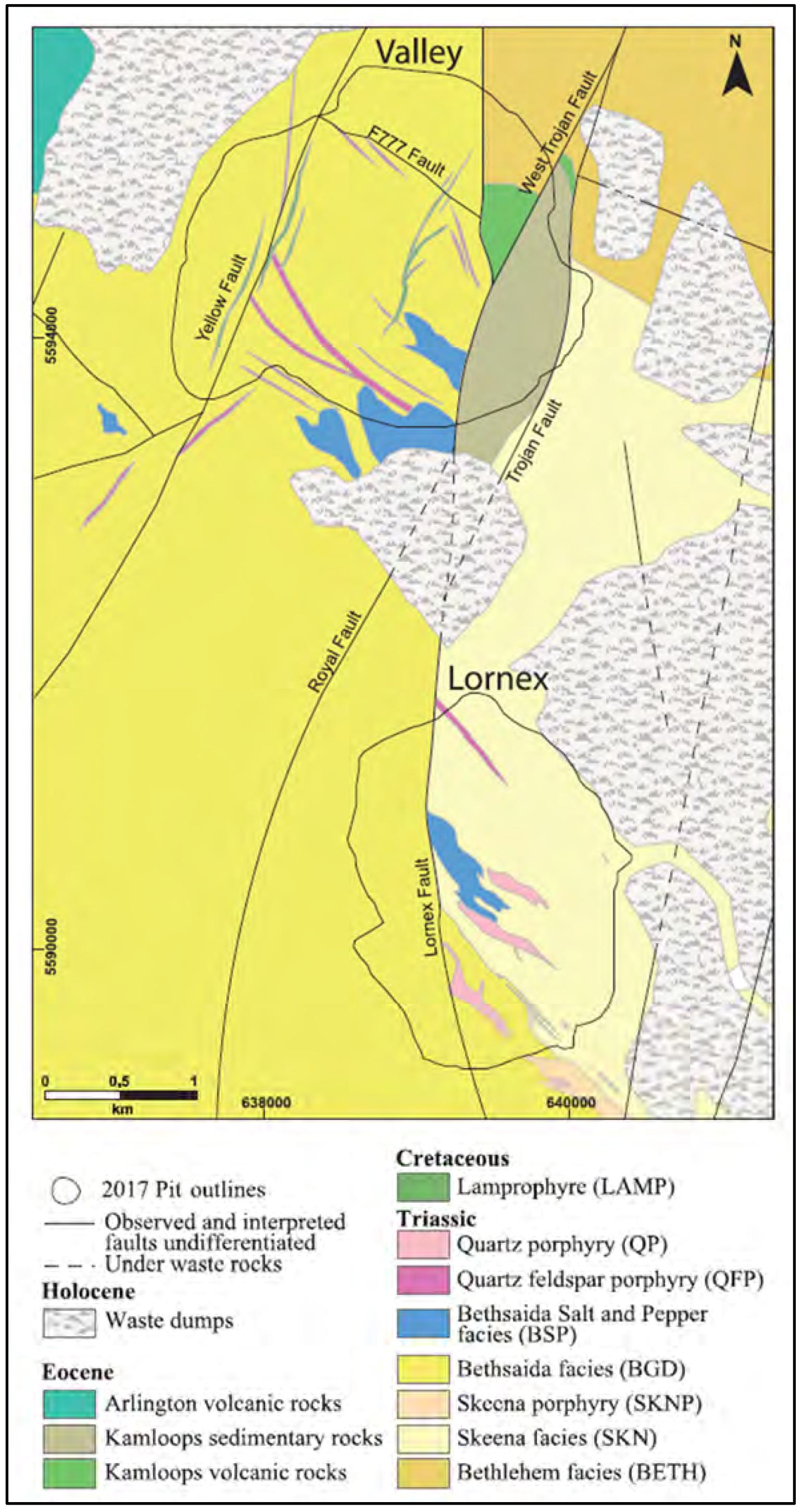
Note: Figure from Ryan et al. (2020)
Figure 7-3: Geology Map, Valley–Lornex Deposit
| October 2025 | Page 7- |
|
|
NI 43-101 Technical Report on Highland Valley Copper Operations British Columbia |

Note: Figure from Ryan et al., (2020). Figure looks northwest.
Figure 7-4: Cross-Section, Valley–Lornex Deposit
| October 2025 | Page 7- |
|
|
NI 43-101 Technical Report on Highland Valley Copper Operations British Columbia |
Table 7-3: Major Faults, Valley–Lornex Deposit
| Fault | Description |
| Lornex fault | North-trending displays roughly 4 km of apparent right-lateral movement with an unknown amount of west-side-up movement. Has a minimum of 100 m of west-side-up movement occurred, although considerably more displacement is likely. The fault is sub-vertical and defined by broad intensely argillic and sericitic-altered damage zones in both the Valley and Lornex deposits. Numerous fault splays of the main Lornex fault have been mapped, including the LF6, LF7 and LF8 faults, which control areas of geotechnical instability within the open pits. |
| Yellow fault system | Set of north–northeast-trending faults that make up the Yellow fault system in the western portion of the Valley pit). No mapped offset has been determined for the Yellow fault, but it locally controls zones of geotechnical concern. |
| Highland Valley fault system | West–northwest-trending series of normal faults related to a graben-shaped topographic feature known as the Highland Valley, located within the center of the batholith. The impact of these Highland Valley faults on the Valley deposit is poorly understood but they appear to down-fault portions of the orebody. The F77 fault is likely part of this fault system, though its location is poorly constrained and the magnitude of displacement on the fault is unknown. Right-lateral and westside-up movement along the Lornex fault likely post-dates the Highland Valley fault system. |
Mineralization is bound by the district-scale Lornex fault to the east in the Valley pit and to the west in the Lornex pit. Both the Lornex and Yellow fault systems display a primary control on the distribution of late sericitic and argillic alteration assemblages.
7.3.1.4 Alteration
Hydrothermal alteration in the Valley–Lornex deposit is characterized by a complex series of crosscutting veins and associated wall rock alteration that are classified into early-, main- and late stage types (Table 7-4). In plan view, footprints of the early- and main-stage alteration events are elongated along a west–northwest axis (Figure 7-5). Late-stage alteration is focused along north-trending structures and less commonly exhibits west–northwest orientations.
7.3.1.5 Mineralization
Copper and molybdenum mineralization is zoned around the centre of the deposit (refer to Figure 7-5), occurring as strongly, moderately, and weakly mineralized concentric halos around the barren core of high temperature quartz veins. Mineralization end abruptly to the east of the deposit centre at the Lornex fault. To the southwest of the deposit centre, an additional weak-to-moderate peripheral mineralized zone trends southwest to northeast. Alteration and mineralization styles suggest this is distal alteration controlled by the Yellow fault, which also trends southwest–northeast.
Sulphides zone from a bornite-rich centre outwards to a mixed zone of bornite–chalcopyrite, a chalcopyrite-dominant zone, and ultimately a peripheral zone where pyrite is more abundant. Late-stage veins associated with sericitic alteration locally overprint this concentric pattern and create narrow, 1–15 m wide, localized high-grade, coarse-grained chalcopyrite ± pyrite sulphide zones.
| October 2025 | Page 7- |
|
|
NI 43-101 Technical Report on Highland Valley Copper Operations British Columbia |
Table 7-4: Alteration Types, Valley–Lornex Deposit
| Alteration Type | Phase | Description |
| Intermediate argillic | Late stage | Defined by the presence of “clay” minerals kaolinite, minor illite, carbonate, and montmorillonite. Forms chalky, white-coloured, patchy pervasive to pervasive alteration and replacement of primary and secondary feldspars. Argillic alteration is locally associated with quartz–iron-carbonate veins. |
| Sericitic | Late stage |
Consists of light green-coloured, patchy, and selective-pervasive or pervasive alteration. Includes often texturally destructive Fe-rich illite and minor carbonate and chlorite. Wide (cm to decimeter-scale), massive quartz ± carbonate ± gypsum veins that contain coarse-grained pyrite, chalcopyrite, and ribbons of molybdenite are often spatially proximal to and associated with the sericitic alteration. Fine-grained chalcopyrite and minor sphalerite are also observed within some zones of sericite alteration. |
| Propylitic | Main stage | Forms a distal halo to the Valley deposit that is located outboard of and overprints earlier potassic alteration. Chlorite veinlets/fracture-coating and the selective replacement of mafic phenocrysts by mixtures of chlorite–epidote–actinolite–carbonate, and of plagioclase by minor amounts of sericite and prehnite compose propylitic alteration. |
| Fractures with discontinuous quartz and chalcopyrite fill, and narrow K-feldspar halos | Main stage | Occur in the periphery of the Valley deposit and are inferred to be part of the main stage alteration. To the southeast of the deposit, a zone of weak K-feldspar veins with center lines of quartz–chalcopyrite occurs, and transitions to the centrally-located potassic–muscovite domain. |
| Sodic–calcic | Main stage | Patchy pervasive to vein-controlled albite–epidote–actinolite and rare garnet alteration occurs at depth and in the southeast of the Valley deposit (spatially coincident with the footwall of the Main QFP dyke). Where intense, this alteration type is texturally destructive and results in the destruction of primary mafic minerals (hornblende and biotite) and sulphide minerals. |
| Potassic–muscovite | Main stage | Characterized by planar quartz–biotite–chalcopyrite ± anhydrite ± minor molybdenite veins. The zone is focused around, crosscuts, and partially overprints the barren core quartz stockwork veins. Medium to coarse-grained muscovite occurs in relict biotite sites, where it replaces secondary biotite (after biotite). Chalcopyrite–K-feldspar stringers (mm-scale) are prominent in the periphery of the Valley deposit and are rarely crosscut by chlorite–carbonate–epidote veinlets (mm-cm scale). |
| Potassic K-feldspar | Early stage | Occurs in the center of the deposit, to the northwest of the barren core quartz stockwork zone. Quartz (± minor anhydrite), chalcopyrite veins with K-feldspar halos and local pervasive K-feldspar alteration appear to cross-cut veins related to the potassic–muscovite alteration. |
| Sulphide-poor quartz veins | Early stage | Complex series of high-density, planar, and sinuous sulphide-poor quartz veins that often lack significant alteration haloes form a zone of intense stockwork pattern that locally introduces up to 40% quartz veins to the host rock by volume. This west–northwest-oriented barren quartz stockwork zone is approximately 700 x 300 m in area, and is located immediately north of the central Bethsaida salt-and-pepper porphyry in the Valley pit. The presence of rhythmic banding suggests multiple pulses of magmatic–hydrothermal fluids, and overall vein textures suggest formation at relatively high temperatures. |
| Micaceous veins | Early stage | Dark-coloured, thin (mm-scale) micaceous (biotite ± muscovite) veins display irregular, diffuse, muscovite–bornite > chalcopyrite halos with no appreciable centre lines. Cut by sinuous and planar barren quartz veins. Secondary biotite selectively replaces primary biotite and is frequently altered to chlorite. |
| October 2025 | Page 7- |
|
|
NI 43-101 Technical Report on Highland Valley Copper Operations British Columbia |

Note: Figure from Ryan et al., (2020).
Figure 7-5: Alteration and Mineralization Map, Valley–Lornex Deposit
| October 2025 | Page 7- |
|
|
NI 43-101 Technical Report on Highland Valley Copper Operations British Columbia |
Mineralization in the Valley deposit is strongly controlled by main-stage potassic–muscovite vein density, with most copper–iron sulphides occurring as vein fill or as coarse-grained disseminations/clots within coarse-grained muscovite vein halos. Chalcocite and lesser covellite occur locally as fine intergrowths within the central zone.
Molybdenite is concentrated in the outer portion of the potassic-muscovite domain and occurs as discrete vein and structurally controlled zones that crosscut main-stage alteration. Molybdenite typically occurs with quartz-carbonate veins, or as fine-grained fracture-coatings. Sulphide-rich crackle breccias can contain fine-grained molybdenite, however these are volumetrically-minor (generally <5 m thick and lack lateral continuity).
The argillic alteration event may also have introduced sulphides and has been observed to locally enrich main-stage mineralization where chalcocite–carbonate reaction rims have been observed on sulphide grains related to main-stage mineralization.
| 7.3.2 | LORNEX DEPOSIT |
7.3.2.1 Deposit Dimensions
The chalcopyrite–bornite footprint of the Lornex deposit is about 2.2 km long by up to 1.5 km wide and is strongly elongated to the north–northwest. The deposit remains open at depth, to the southeast, and to the south. It has been drill tested to approximately 1,200 m depth.
7.3.2.2 Lithologies
The Lornex deposit is situated along the northwest-trending, steeply northeast-dipping contact between the Skeena and Bethsaida facies. The Bethsaida facies is restricted to the southwest part of the deposit, whereas the older and more mafic-mineral-rich Skeena facies is the predominant wall rock at Lornex.
A series of pre-, syn-, and post-mineralization dykes were emplaced within the central portion of the deposit and are flanked by the high-grade zones of mineralization. These intrusions make up the northwest extension of the Gnawed Mountain composite dyke.
The major lithologies are summarized in Table 7-5. The deposit geology was shown in Figure 7-3. An example cross-section is provided in Figure 7-6.
7.3.2.3 Structure
The major structures in the Lornex deposit area were illustrated in Figure 7-3.
The north-trending Lornex fault is surrounded by a 50–100 m-wide structural damage zone of low rock quality and multiple likely related fault planes. The Lornex fault dips steeply to the west and truncates mineralization in the west wall of the Lornex open pit.
| October 2025 | Page 7- |
|
|
NI 43-101 Technical Report on Highland Valley Copper Operations British Columbia |
Table 7-5: Key Lithologies, Lornex Deposit
| Lithology | Phase | Description |
| Lamprophyre dykes | Post-mineral |
Consist of spessartites, and hornblende vogesites. Cut porphyry-related alteration and mineralization, and often exhibit weak iron carbonate alteration along their contacts. |
| Quartz eye aplite (Apl-Q) and aplite/fine-grained granite (Apl-Gr); tan porphyry (TP) | Early mineral | Mostly hosted in Skeena facies and spatially associated with well-mineralized domains. |
| Bethsaida salt-and-pepper porphyry (BSP) | Early mineral | Forms a voluminous northwest- to southeast-trending stock in the centre of the Lornex deposit but also occurs at depth in Bethsaida facies in the south of the deposit. |
| Quartz–feldspar porphyry (QFP), quartz porphyry (QP) | Early mineral | Contain distinct quartz phenocrysts, are the focus of early-stage veins at Lornex. |
| Skeena porphyry (SKNP) | Pre-mineralization | Occurs in the southeast part of the deposit, parallels the Skeena-Bethsaida contact, and can be traced southeast for about 2 km to the Highmont deposit. Displays textural similarities to the Bethsaida facies, but in general, the quartz eyes are less well developed, and the hornblende phenocrysts are texturally similar to those in the Skeena facies. |
| Guichon Creek Batholith (GCB) | Pre-mineralization | Weakly porphyritic granodiorite and monzogranite. |
| October 2025 | Page 7- |
|
|
NI 43-101 Technical Report on Highland Valley Copper Operations British Columbia |

Note: Figure prepared by Teck 2025
Figure 7-6: Cross-Section, Lornex Deposit
7.3.2.4 Alteration
Hydrothermal alteration in the Lornex deposit is also characterized by a complex series of crosscutting veins and associated wall rock alteration that are classified into early-, main- and late-stage types (Table 7-6). Alteration is similar to that of the Valley deposit previously described but with increased argillic and sericitic overprints leading to overall softer ore. The alteration system in the Valley–Lornex area was shown in Figure 7-5.
7.3.2.5 Mineralization
The mineralization zonation was shown in Figure 7-5.
Mineralization is dominantly vein and fracture-controlled, and to a lesser extent, disseminated in mafic mineral sites.
| October 2025 | Page 7- |
|
|
NI 43-101 Technical Report on Highland Valley Copper Operations British Columbia |
Table 7-6: Alteration Types, Lornex Deposit
| Alteration Type | Phase | Description |
| Sericitic | Late stage | Northeast-trending, 0.25–1 m wide, widely-spaced (hundreds of metres) quartz–carbonate–sulphide veins with sericite halos (D-veins) crosscut the main-stage alteration facies and associated veins. |
| Intermediate argillic | Late stage | Comprises kaolinite ± montmorillonite ± smectite. Prominent in the southeast of the Lornex deposit and locally along the Lornex fault. Dominantly structurally controlled and focused in fractured or gouge-rich fault zones and proximal to dyke margins. |
| Sodic–calcic | Main stage |
Albite alteration-associated sodic–calcic facies occur as pervasive, texturally destructive, Fe- and Cu- poor albite alteration zones, patchy pervasive zones, and mostly as halos around epidote and actinolite veins. Crosscutting relationships are cryptic and show evidence that albite alteration occurred both before and after main-stage Cu mineralization. Albite–epidote–actinolite ± garnet alteration is focused in the southeast portion of the Lornex pit, in and around the Skeena porphyry. |
| Propylitic | Main stage | Best developed within the Skeena porphyry in the east of the Lornex deposit as selective replacement of biotite and hornblende by chlorite and chlorite–epidote ± carbonate veins. |
| Potassic–muscovitic | Main stage | Consists of planar quartz–bornite>chalcopyrite ± anhydrite veins with coarse-grained muscovite ± K-feldspar halos and narrow (1–5 mm) planar muscovite–quartz–bornite–chalcopyrite veins. Coincides with the highest copper grades and bornite-rich domains at Lornex. |
| Potassic–biotitic and K-feldspar | Early stage | Comprises secondary biotite ± quartz ± chalcopyrite ± magnetite forming shreddy-textured aggregates that replace primary biotite and hornblende or as millimetre-scale irregular veins. Minor magnetite occurs as fine-grained masses, locally pseudomorphing primary mafic phenocrysts. Sinuous, copper-poor quartz stockwork and conjugate veins are generally associated with a pervasive K-feldspar alteration zone (potassic-K-feldspar facies). Below the potassic-K-feldspar facies zone and mostly hosted in the Skeena porphyry, a zone of planar barren quartz veins without halos forms a northwest-plunging, elliptical dome of low-grade mineralization. |
| Sulphide-poor quartz veins | Early stage | Complex series of high-density, planar, and sinuous sulphide-poor quartz veins that often lack significant alteration haloes form a zone of intense stockwork pattern that locally introduces up to 40% quartz veins to the host rock by volume. These occurs at depth and in the central portion of the deposit overlapping with the central dyke complex. |
| October 2025 | Page 7- |
|
|
NI 43-101 Technical Report on Highland Valley Copper Operations British Columbia |
Bornite and chalcopyrite mineralization typically is hosted in planar, centimetre-scale quartz veins or as narrow sulphide-only veins. Sulphides occur as 1 mm size disseminations to 2–5 mm clots, centre-lines in quartz veins, and fine-grained (<1 mm) selective replacements of hornblende and biotite in vein halos. Disseminated sulphides are more common in the Lornex deposit than in the Valley deposit.
Most of the copper mineralization is spatially and temporally associated with the potassic-muscovite facies, and bornite occurs in two to three discontinuous, northwest-trending domains which flank the central dyke complex. The highest concentrations of molybdenite are mostly coincident with the copper mineralization in the Lornex deposit. Quartz–molybdenite–chalcopyrite ± bornite veins with weak sericite halos are inferred to post-date the planar quartz-bornite veins with coarse muscovite halos, although definitive cross-cutting relationships supporting this interpretation are lacking.
Molybdenite typically occurs as blebs or disseminations at the margin of the quartz veins or as rhythmic microcrystalline layers. Minor sphalerite, galena, tetrahedrite, and pyrrhotite occur as accessory sulphides.
| 7.3.3 | HIGHMONT DEPOSIT |
The Highmont is approximately 1.6 km southeast of the Valley–Lornex deposit.
7.3.3.1 Deposit Dimensions
Bornite–chalcopyrite mineralization at the Highmont deposit occurs in several discrete porphyry centres with a total footprint of 2 x 1.1 km and is elongate to the northwest. The deposit remains open at depth and to the east. It has been drill-tested to approximately 300 m depth.
7.3.3.2 Lithologies
The Highmont deposit is hosted within the Skeena granodiorite phases of the Gnawed Mountain composite dyke. A description of these key lithologies is provided in Table 7-7. A geology map is included as Figure 7-7.
7.3.3.3 Structure
Post-mineral faulting of the Highmont deposit has resulted in local juxtaposition of alteration and mineralization domains (Figure 7-8) but has not significantly dissected the deposit in the same way as the Lornex fault dissected the Valley–Lornex deposit.
Northeast-trending normal faults result in local horst and graben development within the deposit. The Waterhole fault at the eastern side of the deposit strikes northeast, dipping 60° west. Movement on the fault was largely or wholly post-mineral. Apparent left-lateral horizontal displacement is evident where the fault crosses the Gnawed Mountain dyke. The apparent normal displacement has down-faulted the deposit on the west side of the fault. This resulted in juxtaposition of the potassic–muscovite alteration to the west and deep sodic–calcic and potassic-K-feldspar to the east.
The West Boundary fault (located on the western side of the deposit) displays the opposite sense of apparent normal displacement and juxtaposes different alteration styles.
| October 2025 | Page 7- |
|
|
NI 43-101 Technical Report on Highland Valley Copper Operations British Columbia |
Table 7-7: Key Lithologies, Highmont Deposit
| Lithology | Phase | Description |
| Basalt to andesite dykes | Post-mineral | Minor, display poor continuity. |
| Lamprophyre dykes | Post-mineral | |
| Gnawed Mountain composite dyke | Pre- to syn-mineral |
Weakly mineralized intrusion. Three sub-types: o GMCDa: pre-mineral porphyry, crowded phenocrysts of plagioclase, quartz, biotite, and hornblende in an aplitic matrix. o GMCDb: syn-mineral porphyry, phenocrysts of plagioclase, quartz, biotite, and hornblende in a sugary matrix o GMCDc. syn-mineral porphyry, phenocrysts of plagioclase, quartz, biotite, and tourmaline in an aplitic matrix. |
| Skeena phase quartz-feldspar porphyry | Pre-mineral | Coarse grained, seriate crowded porphyry. Phenocrysts of plagioclase, quartz, K-feldspar, hornblende, and biotite. |
| Guichon Creek Batholith (GCB) | Pre-mineralization | Weakly porphyritic granodiorite and monzogranite. |
7.3.3.4 Alteration
Alteration assemblages in the Highmont deposit are mineralogically similar to alteration in the Valley–Lornex deposit but are generally less intense. Sheeted and stockwork veins control the distribution of the bulk of the mineralization, but multiple breccia bodies have also been identified. Copper mineralization is broadly co-incident with domains of increased K-feldspar-biotite, muscovite, and sericite alteration. A summary of the major alteration types is included as Table 7-8, and a location plan for the alteration zones is provided as Figure 7-9 (overprinting alteration) and Figure 7-10 (high-temperature alteration).
7.3.3.5 Mineralization
The Highmont deposit contains several low-grade mineralized zones in Skeena quartz diorite. The Gnawed Mountain porphyry dyke trends west–northwest and separates two actively mined ore zones (West pit and East pit) from mineralization in Highmont south. Highmont copper and molybdenum mineralization is zoned from the centres of the three Highmont pits.
Copper mineralization occurs as bornite, chalcopyrite and lesser chalcocite within quartz and/or white mica veins, and to a lesser degree as hydrothermal breccia cement and infill.
The generalized sulphide mineral distribution map (refer to Figure 7-8) indicates a roughly concentric distribution of bornite–chalcopyrite and pyrite centered in the east of the deposit and extending toward the northwest along the contacts of the Gnawed Mountain composite dyke.
A chalcopyrite–specular hematite zone crosscuts the bornite zone controlled by the late hydrothermal breccia which cross-cuts the Gnawed Mountain composite dyke.
| October 2025 | Page 7- |
|
|
NI 43-101 Technical Report on Highland Valley Copper Operations British Columbia |
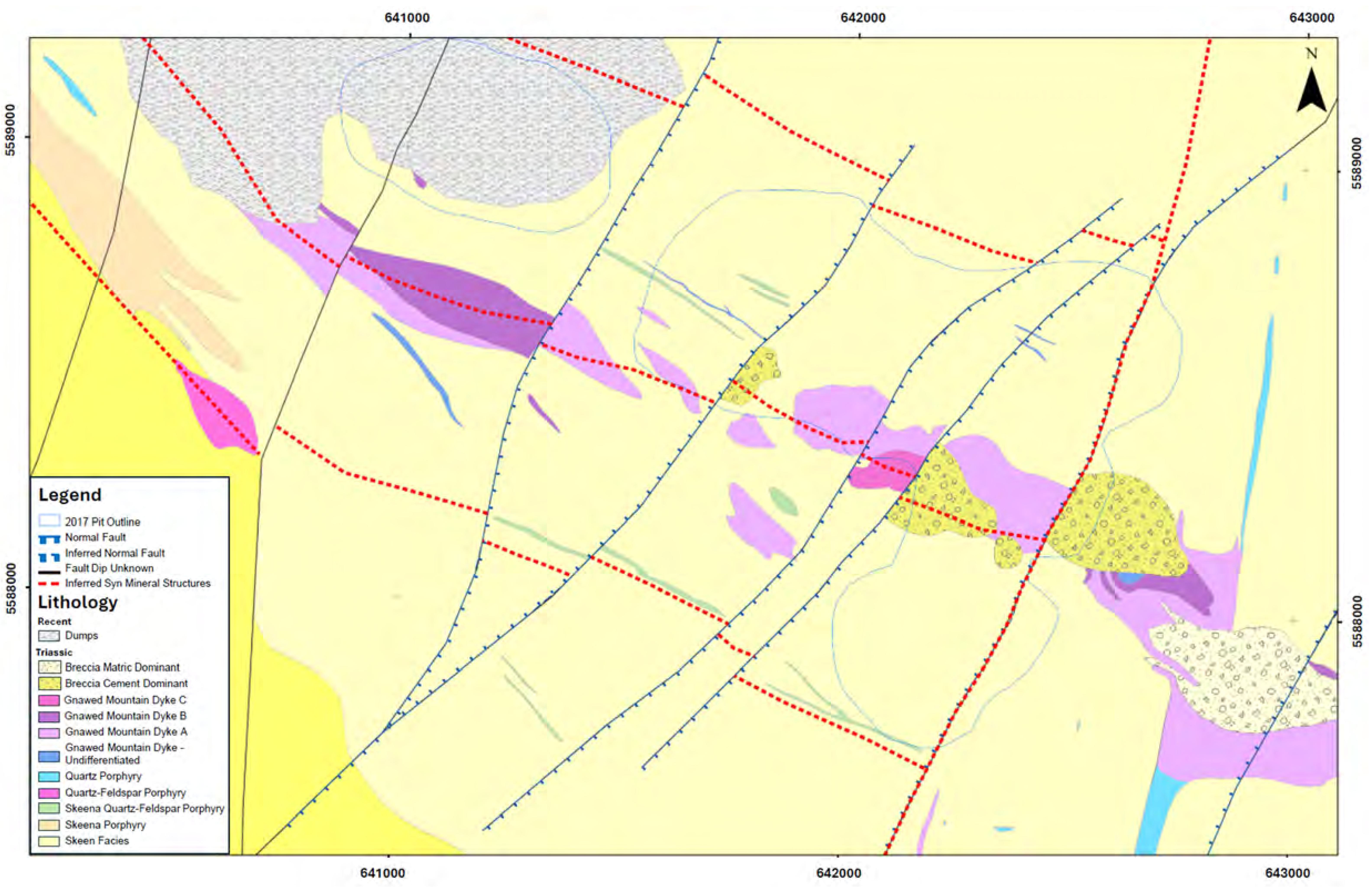
Note: Figure prepared by Teck, 2023.
Figure 7-7: Geology Map, Highmont Deposit
| October 2025 | Page 7- |
|
|
NI 43-101 Technical Report on Highland Valley Copper Operations British Columbia |

Note: Figure prepared by Teck, 2023.
Figure 7-8: Mineralization Map Showing Major Structures, Highmont Deposit
| October 2025 | Page 7- |
|
|
NI 43-101 Technical Report on Highland Valley Copper Operations British Columbia |
Table 7-8: Alteration Types, Highmont Deposit
| Alteration Type | Phase | Description |
| Argillic | Late | Occurs as pervasive replacement of the host rock or selective-pervasive replacement of mafic and felsic phenocrysts. It also occurs as vein haloes to cream-coloured quartz–carbonate veins or iron-carbonate stringers. |
| Sericitic | Late | Locally associated with late 0.1–0.5 m wide quartz–sulphide veins characterized by coarse copper sulphides (bornite, chalcopyrite) and “ribbons” of molybdenite. |
| Hydrothermal cement-dominant breccia | Intermediate | Crosscut the early veins. The largest of these is a 300 m x 120 m northwest-trending sub-vertical body located within the central part the of Highmont deposit. The geometry of this body is poorly defined at depth. The breccia cement commonly consists of quartz, specular hematite, sulphide minerals (dominantly chalcopyrite), tourmaline and epidote. Alteration mineralogy inside the breccia body appears to form a zonation pattern characterized by clasts with albite alteration rinds at higher elevation that transition to K-feldspar alteration rinds at depth. |
| Sodic-calcic | Intermediate | Prominent to the southwest and in the central portion of the deposit, between the Highmont East pit and the planned western extension of the South pit. This alteration type commonly comprises patchy zones of veins and crackle breccias with albite–epidote ± actinolite infill and wall rock alteration. The timing of this alteration is not clearly understood; however, there is some evidence for multiple fluid pulses that resulted in this alteration assemblage. It is also possible that the fluids responsible for this alteration assemblage caused the local remobilization of copper mineralization. Like the early alteration types, the contacts of this alteration zone are generally gradational and poorly constrained by drilling. This alteration typically results in increased in-situ rock hardness. |
| Biotite–sulphide and quartz–sulphide veins with K-feldspar halos | Early | Typically bornite-rich and associated metallic-grey chalcocite, which appears to be hypogene in nature. The biotite–sulphide-dominant zone transitions laterally to a zone of quartz–sulphide veins with muscovite halos that are characterized by increased chalcopyrite and molybdenite content. |
| October 2025 | Page 7- |
|
|
NI 43-101 Technical Report on Highland Valley Copper Operations British Columbia |

Note: Figure prepared by Teck, 2023.
Figure 7-9: Overprinting Alteration Plan, Highmont Deposit
| October 2025 | Page 7- |
|
|
NI 43-101 Technical Report on Highland Valley Copper Operations British Columbia |

Note: Figure prepared by Teck, 2023.
Figure 7-10: High Temperature Alteration Plan, Highmont Deposit
| October 2025 | Page 7- |
|
|
NI 43-101 Technical Report on Highland Valley Copper Operations British Columbia |
A small zone of black-coloured sooty chalcocite occurred near surface in the eastern portion of the deposit, which is interpreted to be potentially supergene. It is believed to be largely mined out. What remains is located beneath a cap of limonite and weak malachite developed in association with strong clay alteration.
A cross section through the lithologies and mineralization of the Highmont deposit is included as Figure 7-11.
| 7.3.4 | BETHLEHEM DEPOSIT |
The Bethlehem deposits formed approximately 5 km northeast of the original location of the Valley–Lornex deposit. Due to movement along the Lornex Fault it is now 3.5 km east–northeast of the Valley pit.
7.3.4.1 Deposit Dimensions
Bornite–chalcopyrite mineralization at the Bethlehem deposits occurs in several discrete porphyry centres with a total footprint of 2.5 x 1.1 km. The mineralized zones are elongate to the northwest. The deposits remain open locally at depth and to the south. There is some evidence that Bethlehem may continue to the south. It has been drilled tested to approximately 700 m depth.
7.3.4.2 Lithologies
The Bethlehem deposit is located within a northwest-trending embayment in the contact between the Guichon subfacies and Bethlehem facies of the batholith. Multiple mineralized centres (Huestis, Jersey, East Jersey, and Iona) with overlapping hydrothermal footprints make up the larger porphyry system collectively termed "Bethlehem".
The deposits are hosted in Guichon and various Bethlehem facies/sub-facies intrusions, and in poorly-sorted clastic-matrix breccias that are mostly contained within the Bethlehem sub-facies intrusions.
Multiple generations of matrix-rich, subangular to rounded, pebble- to boulder- sized clast breccias and locally cemented (hydrothermal precipitate and igneous) breccia bodies crosscut and are themselves cut by a series of syn-, and post-mineral dykes. Mineralization as shown by sulphide species and alteration domains is focused on and zones about the breccia bodies and syn-mineral intrusions. The breccias have subvertical contacts with wall rocks.
Five mineralogically and texturally distinct facies of late- and post-mineral intrusions crosscut main-stage mineralization in the Bethlehem area. These intrusions occur as dykes and stocks, with overall northerly trends and elongation, respectively.
The key lithologies in the Bethlehem area are summarized in Table 7-9. A geology map for the Bethlehem area is included as Figure 7-12, and Figure 7-13 is a cross-section through the deposit.
| October 2025 | Page 7- |
|
|
NI 43-101 Technical Report on Highland Valley Copper Operations British Columbia |
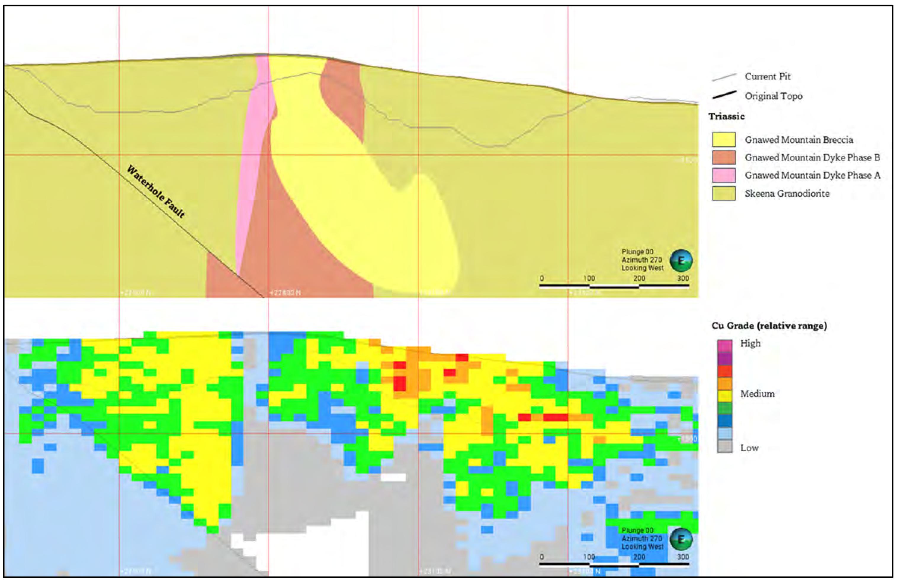
Note: Figure prepared by Teck, 2025.
Figure 7-11: Lithology and Mineralization Sections, Highmont Deposit
| October 2025 | Page 7- |
|
|
NI 43-101 Technical Report on Highland Valley Copper Operations British Columbia |
Table 7-9: Key Lithologies, Bethlehem Deposit
| Lithology | Phase | Description |
| Spud porphyry stock | Post-mineral | North-trending, characterized by crowded plagioclase–quartz–hornblende phenocrysts in a sugary ground mass. The quartz eyes are texturally similar to those of the Bethsaida facies of the of the Guichon Creek Batholith. |
| Late Jersey (LJSK) and Late Iona (LISK) stocks | Post-mineral | The Late Jersey stock is not exposed at surface. The Late Iona stock has some textural similarities to the feldspar and quartz-phyric crowded porphyry and feldspar-phyric crowded porphyry intrusions and may be a younger, related phase, whereas the Late Jersey stock displays textural and whole-rock geochemical similarities to the Skeena facies of the Guichon Creek Batholith. |
| Feldspar and quartz-phyric crowded porphyry (FQPC); feldspar-phyric crowded porphyry (FPC) dykes | Post-mineral | Characterized by crowded plagioclase–hornblende crystals, with the feldspar and quartz-phyric crowded porphyry containing up to 10% quartz eyes. The feldspar and quartz-phyric crowded porphyry is generally cut by the feldspar-phyric crowded porphyry, though the observed inverse contact relationship suggests a close temporal association. These post-mineral dykes form 10–30 m wide, north- and northeast-trending, steeply west-dipping intrusions. They are locally crosscut by late-mineral veins that can contain minor disseminated chalcopyrite. Cross-cut earlier potassic alteration domains; display propylitic alteration. |
| Feldspar-quartz-phyric Bethlehem porphyry (BTHMP) dykes | Syn-mineral | Contain a distinctive groundmass of quartz-K-feldspar (20–70%) and locally trend northeast. Internal chilled contacts within the units indicate that they comprise a series of nested intrusions. These dykes are interpreted to be syn-mineral, often with mutually cross-cutting relationships with the hydrothermal breccias, indicative of multiple dyke emplacement events. |
| Feldspar-phyric, mafic-poor porphyry (FP) dykes | Syn-mineral | Characterized by distinctive feldspar laths with minor changes in abundance of quartz, hornblende, and biotite phenocrysts within an aphanitic to finely crystalline groundmass. Vary in form from tabular dykes with planar, chilled margins to complex zones of dykelets and breccia with cryptic contact relationships. Dykes locally occur as an igneous cement to the breccias, as angular clasts within the breccias, or as ragged fluidal clasts in the breccia. |
| Feldspar-phyric, mafic-bearing porphyry (FPM) dyke | Pre-mineral | Forms a 5–15 m, north-trending dyke to the east of the East Jersey breccia and a complex series of north- and northeast-trending dykes to the east of the Iona porphyry centre. When observed, it is chilled against the Guichon granodiorite. |
| Guichon Creek Batholith (GCB) | Pre-mineral | Equigranular and porphyritic phases of the Guichon and Bethlehem phases of the batholith. |
| October 2025 | Page 7- |
|
|
NI 43-101 Technical Report on Highland Valley Copper Operations British Columbia |

Note: Figure from Ryan et al., (2020).
Figure 7-12: Lithology, Alteration, and Mineralization Map, Bethlehem Deposit
| October 2025 | Page 7- |
|
|
NI 43-101 Technical Report on Highland Valley Copper Operations British Columbia |
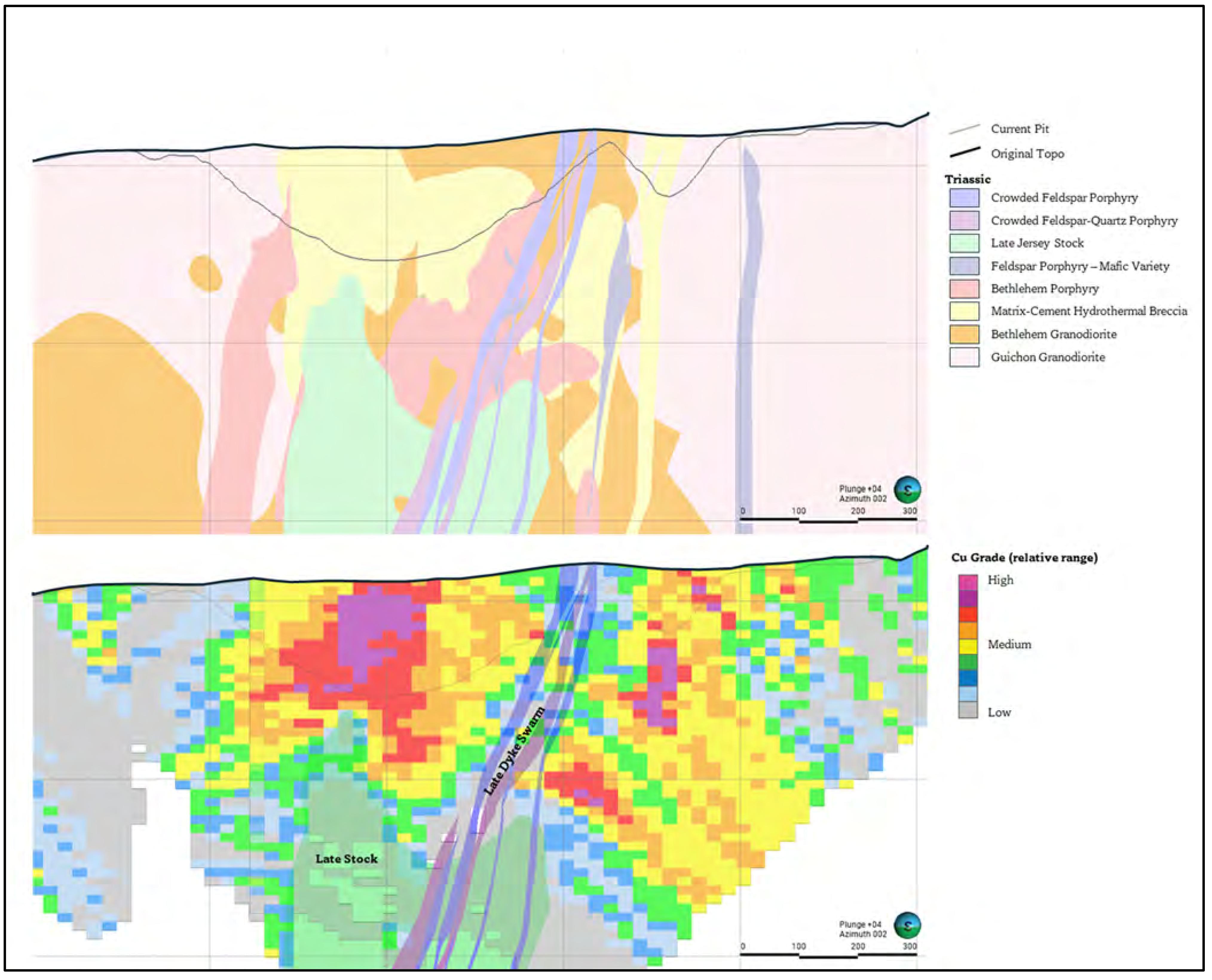
Note: Figure prepared by Teck, 2025
Figure 7-13: Geological Cross-Section, Bethlehem Deposit
7.3.4.3 Structure
North- and northeast-trending structures are present throughout the Bethlehem deposit area (refer to Figure 7-12). The lack of good marker horizons inhibits robust estimation of displacement along these structures. Apparent changes in alteration distribution across northeast faults, however, suggest local horst and graben development with Jersey and Iona.
North-trending structures often display the strongest deformation, characterized by thick damage zones surrounding discrete gouge intervals or localized intervals of foliated rock. The four most significant structures are the north-trending Huestis, Jersey, Iona, and Snowstorm fault systems. These likely accommodate right-lateral movement within the batholith typically attributed to the Lornex fault.
| October 2025 | Page 7- |
|
|
NI 43-101 Technical Report on Highland Valley Copper Operations British Columbia |
A single, prominent west-northwest-trending fault, the North Highland Valley fault, occurs to the south of the deposit. A large fault scarp related to this structure is present east-southeast of Bethlehem. The north- and northwest-trending structures are interpreted as being long-lived but show evidence of reactivation and locally appear to truncate the northeast-trending fault sets.
7.3.4.4 Alteration
Alteration and mineralization in Bethlehem are dominantly controlled by vein and breccia distribution, with relatively minor pervasive alteration or disseminated sulphides in wall rocks. The former Jersey, East Jersey, Iona, and Huestis open pits each appear to be separate hydrothermal centres, but with alteration and mineralization footprints that partially overlap (refer to Figure 7-12).
Vein density and potassic and sericite alteration intensity decrease rapidly (tens of metres) away from breccia and the Guichon granodiorite wall rock contact. Three main stages of alteration are recognized: an early-stage weak potassic biotite facies; a main-stage potassic K- feldspar and biotite and sericitic alteration facies; and a late-stage, grade-destructive sodic–calcic event.
Hydrothermal alteration is classified into early-, main- and late-stage types as shown in Table 7-10 and shown on Figure 7-12.
7.3.4.5 Mineralization
Sulphide mineral zonation at Bethlehem is complicated by the presence of multiple porphyry centres and their overlapping alteration and mineralization footprints (refer to Figure 7-12).
The early-stage potassic event generated low-grade copper mineralization, comprising bornite–chalcocite cores that zone to a broader chalcopyrite-dominant zone following the Bethlehem–Guichon contact. Sulphide minerals related to this event are generally <0.5% of the rock by volume.
Main-stage mineralization within each centre is characterized by bornite-dominant cores that transition to chalcopyrite-rich domains and then to outer pyritic ± specular hematite domains. Sulphides within these zones can exceed 2% of the rock volume. The highest-grade mineralization is associated with biotite and sericite alteration facies and is spatially coincident with breccia and syn-mineral feldspar–quartz-phyric Bethlehem porphyry dykes, whereas lower grades commonly occur with K-feldspar alteration.
Molybdenite forms discontinuous halos around most of the main-stage alteration centres at Bethlehem and is generally coincident with sericite alteration zones. The most significant concentrations of molybdenite occur in the southern breccia in Iona as localized molybdenite–quartz cement with sericite alteration. Overall, however, molybdenite concentrations are lower at Bethlehem compared to other deposits in the Highland Valley district.
Oxidation of the sulphide minerals resulted in the development of malachite, azurite, and chrysocolla on fracture surfaces. Mixed copper oxide and sulphide zones occur to a depth of about 10 m across the deposit and deepen to the south.
| October 2025 | Page 7- |
|
|
NI 43-101 Technical Report on Highland Valley Copper Operations British Columbia |
Table 7-10: Alteration Types, Bethlehem Deposit
| Alteration Type | Phase | Description |
| Quartz–carbonate–sulphide–specular hematite | Post-mineral | Late structurally controlled event forming north- and northeast-trending veins with pervasive pale green–white mica (sericite), chlorite, and epidote halos. Locally associated with high-grade chalcopyrite mineralization. |
| Sodic–calcic | Post-mineral | Spatially associated with the late stocks, forming an alteration front that extends 10–100 m into the surrounding host rock. Actinolite, garnet, and minor magnetite are most intense beneath the Jersey and East Jersey open pits. |
| Propylitic | Syn-mineral | Occurs as vein-controlled epidote–chlorite and selective pervasive chlorite-epidote extending beyond the limit of detailed mapping. Chlorite is often shreddy, suggesting overprinting of earlier secondary biotite. |
| Sericitic | Syn-mineral | Fine-grained grey–white mica pervasively alters the upper portions of breccia bodies and forms halos along he margins of quartz veining. These zones display elevated pyrite and molybdenum concentrations. |
| Potassic– K-feldspar |
Syn-mineral |
Forms halos of sinuous to planar quartz veins and locally as pervasive K-feldspar alteration that crosscuts early potassic biotite-rich veins within the central-deep portions of each porphyry centre. The K-feldspar-rich potassic zone transitions gradually upwards into a biotite-dominant zone, and up and outwards into a domain where sericite veins and halos are dominant. Breccia formation is associated with this main-stage alteration; also zoned from deep K- feldspar-rich, mid biotite-rich and upwards into more sericite-dominated alteration. |
| Potassic | Early-stage | Biotite dominated; primarily focused along the Guichon–Bethlehem facies contact. Characterized by <1–1 mm planar veins of bornite–chalcopyrite ± quartz ± biotite, typically associated with narrow biotite halos. Rare quartz, either within quartz–chalcopyrite–bornite veins or as local sinuous quartz veins. |
| October 2025 | Page 7- |
|
|
NI 43-101 Technical Report on Highland Valley Copper Operations British Columbia |
| 8 | DEPOSIT TYPES |
| 8.1 | Introduction |
The deposits are considered to be classic examples of porphyry copper–molybdenum deposits.
The following discussion of the typical nature of porphyry-copper deposits is sourced from Sillitoe, (2010), Singer et al., (2008), and Sinclair (2007).
| 8.2 | Deposit Type Description |
| 8.2.1 | GEOLOGICAL SETTING |
Porphyry copper systems commonly define linear belts, some many hundreds of kilometres long, as well as occurring less commonly in apparent isolation. The systems are closely related to underlying composite plutons, at paleo-depths of 5 km to 15 km, which represent the supply chambers for the magmas and fluids that formed the vertically elongate (>3 km) stocks or dyke swarms and associated mineralization.
Commonly, several discrete stocks are emplaced in and above the pluton roof zones, resulting in either clusters or structurally controlled alignments of porphyry copper systems. The rheology and composition of the host rocks may strongly influence the size, grade, and type of mineralization generated in porphyry copper systems. Individual systems have life spans of circa 100,000 years to several million years, whereas deposit clusters or alignments, as well as entire belts, may remain active for 10 million years or longer.
Deposits are typically semicircular to elliptical in plan view. In cross-section, ore-grade material in a deposit typically has the shape of an inverted cone with the altered, but low-grade, interior of the cone referred to as the “barren” core. In some systems, the barren core may be a late-stage intrusion.
The alteration and mineralization in porphyry copper systems are zoned outward from the stocks or dyke swarms, which typically comprise several generations of intermediate to felsic porphyry intrusions. Porphyry copper–gold–molybdenum deposits are centered on the intrusions, whereas carbonate wall rocks commonly host proximal copper–gold skarns and less commonly, distal base metal and gold skarn deposits. Beyond the skarn front, carbonate-replacement copper, and/or base metal–gold deposits, and/or sediment-hosted (distal-disseminated) gold deposits can form. Peripheral mineralization is less conspicuous in non-carbonate wall rocks but may include base metal- or gold-bearing veins and mantos. Data compiled by Singer et al. (2008) indicate that the median size of the longest axis of alteration surrounding a porphyry copper deposit is 4–5 km, while the median size area of alteration is 7–8 km2.
High-sulphidation epithermal deposits may occur in lithocaps above porphyry-copper deposits, where massive sulphide lodes tend to develop in their deeper feeder structures, and precious metal-rich, disseminated deposits form within the uppermost 500 m.
Figure 8-1 shows a schematic section of a porphyry copper deposit illustrating the relationships of the lithocap to the porphyry body, and associated mineralization styles.
| October 2025 | Page 8- |
|
|
NI 43-101 Technical Report on Highland Valley Copper Operations British Columbia |
| 8.2.2 | MINERALIZATION |
Porphyry copper mineralization occurs in a distinctive sequence of quartz-bearing veinlets as well as in disseminated forms in the altered rock between them. Magmatic–hydrothermal breccias may form during porphyry intrusion, with some breccias containing high-grade mineralization because of their intrinsic permeability. In contrast, most phreatomagmatic breccias, constituting maar–diatreme systems, are poorly mineralized at both the porphyry copper and lithocap levels, mainly because many such phreatomagmatic breccias formed late in the evolution of systems, and the explosive nature of their emplacement fails to trap mineralizing solutions.
Copper–ore mineral assemblages are a function of the chemical composition of the fluid phase and the pressure and temperature conditions affecting the fluid. In primary, unoxidized or non-supergene-enriched ores, the most common ore–sulphide assemblage is chalcopyrite ± bornite, with pyrite and minor amounts of molybdenite. In supergene-enriched ores, a typical assemblage can comprise chalcocite + covellite ± bornite, whereas, in oxide ores, a typical assemblage could include malachite + azurite + cuprite + chrysocolla, with minor amounts of minerals such as carbonates, sulphates, phosphates, and silicates. Typically, the principal copper sulphides consist of millimetre-scale grains but may be as large as 1–2 cm in diameter and, rarely, pegmatitic (larger than 2 cm).
| 8.2.3 | ALTERATION |
Alteration zones in porphyry copper deposits are typically classified based on mineral assemblages. In silicate-rich rocks, the most common alteration minerals are K-feldspar, biotite, muscovite (sericite), albite, anhydrite, chlorite, calcite, epidote, and kaolinite. In silicate-rich rocks that have been altered to advanced argillic assemblages, the most common minerals are quartz, alunite, pyrophyllite, dickite, diaspore, and zunyite.
In carbonate rocks, the most common minerals are garnet, pyroxene, epidote, quartz, actinolite, chlorite, biotite, calcite, dolomite, K-feldspar, and wollastonite. Other alteration minerals commonly found in porphyry-copper deposits are tourmaline, andalusite, and actinolite. Figure 8-2 shows the alteration assemblage of a typical porphyry-copper system.
Porphyry copper systems are initiated by injection of oxidized magma saturated with sulphur- and metal-rich, aqueous fluids from cupolas on the tops of the subjacent parental plutons. The sequence of alteration–mineralization events is principally a consequence of progressive rock and fluid cooling, from >700° to <250°C, caused by solidification of the underlying parental plutons and downward propagation of the lithostatic–hydrostatic transition.
| October 2025 | Page 8- |
|
|
NI 43-101 Technical Report on Highland Valley Copper Operations British Columbia |
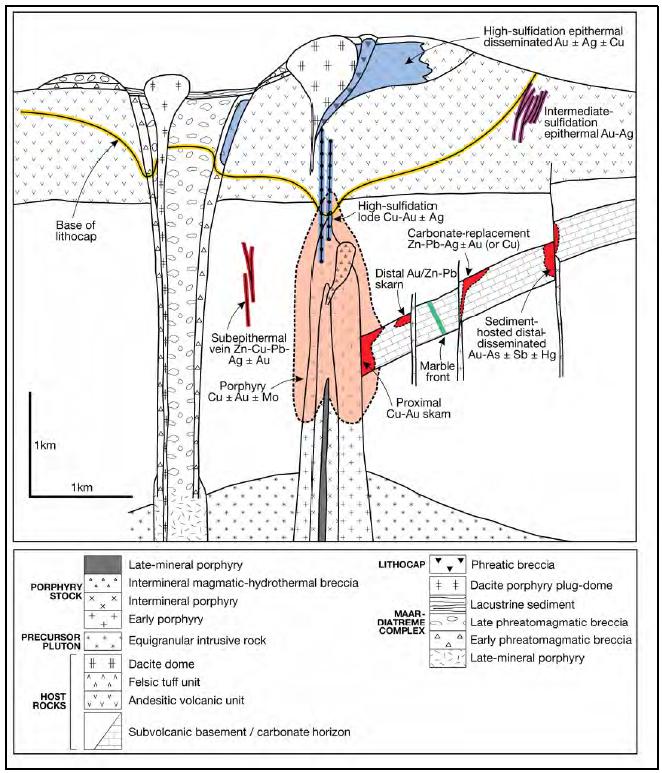
Note: Figure from Sillitoe, 2010.
Figure 8-1: Schematic Section, Porphyry Copper Deposit
| October 2025 | Page 8- |
|
|
NI 43-101 Technical Report on Highland Valley Copper Operations British Columbia |

Note: Figure from Sillitoe (2010)
Figure 8-2: Schematic Section Showing Typical Alteration Assemblages
Once the plutonic magmas stagnate, the high-temperature, generally two-phase hyper-saline liquid and vapour responsible for the potassic alteration and contained mineralization at depth and early overlying advanced argillic alteration, respectively, gives way, at <350°C, to a single-phase, low-to-moderate-salinity liquid that causes the sericite–chlorite and sericitic alteration and associated mineralization. This same liquid also is a source for mineralization of the peripheral parts of systems, including the overlying lithocaps.
The progressive thermal decline of the systems combined with syn-mineral paleo-surface degradation results in the characteristic overprinting (telescoping) and partial to total reconstitution of older by younger alteration–mineralization types. Meteoric water is not required for formation of this alteration–mineralization sequence although its late ingress is common.
| 8.3 | QP Comment on Item 8 “Deposit Types” |
The QP is of the opinion that a porphyry copper deposit type is an appropriate model for exploration and for support of the geological models used in Mineral Resource estimation.
| October 2025 | Page 8- |
|
|
NI 43-101 Technical Report on Highland Valley Copper Operations British Columbia |
| 9 | EXPLORATION |
Given the long mining history, early-stage exploration activities have been superceded by drill campaigns.
| 9.1 | Grids and Surveys |
The operations use a local mine grid system that is convertible to standard WGS84, NAD83 and UTM coordinates. The original grid was developed by McElhanney Surveying and Engineering Ltd. in the early 1970s. The centre of the grid is roughly in the middle of the Valley pit with coordinates of 100,000 ft. N and 100,000 ft. E.
Surveying onsite is completed by one, or a combination of, the following methods:
| · | High-precision global positioning system (GPS) surveying; |
| · | Total station; |
| · | Unmanned aerial vehicle (UAV) photogrammetry and video acquisition; |
| · | Laser scanning. |
| 9.2 | Geological Mapping |
Geological mapping has been completed as part of numerous exploration campaigns over the historic of exploration in the Guichon batholith. Modern mapping campaigns (post-2010) were completed by Teck geologists alongside Canadian Mining Innovation Council researchers. These were completed at two scales:
| · | 1:10,000-scale district geological mapping; |
| · | 1:2,000-scale mapping of specific target areas. |
Detailed surface mapping was completed in the following areas:
| · | In the immediate vicinity of the Valley, Lornex, Highmont, and Bethlehem pits; |
| · | To the south of the Valley pit stretching towards the historic Alwin mine; |
| · | To the east of Highmont stretching to the historic Highmont TSF; |
| · | Over the Joe-Sheba target which is located 4.3 km east southeast of the mill; |
| · | Over the Athena target which is located 9 km due east of the mill; |
| · | Over the Bethlehem North target which is located 8.7 km due north of the mill, adjacent to Getty Copper’s Getty North deposit. |
A compilation of modern surface mapping stations in contained within an acQuire data base. The results of this mapping is included in the geological maps included in Section 7.
| October 2025 | Page 9- |
|
|
NI 43-101 Technical Report on Highland Valley Copper Operations British Columbia |
| 9.3 | Geochemical Sampling |
The record of geochemical sampling is generally restricted to modern work (post-2010) with a limited amount of historic information available from BC Assessment Report Indexing System (ARIS) reports. The most significant geochemical datasets are related to the following:
| · | Teck district exploration 2014–2019: As part of yearly district mapping and detailed target mapping rock grab samples were collected on a regular basis. Samples were used to validate the underlaying geology and for use in trace element exploration vectoring. SWIR measurements were also collected from chip samples from most geological stations from 2016–2019. This work defined the Bethlehem North, Athena, and Gary targets leading to the drill testing of the Athena and Gary targets, as well as refining the understanding of the Bethsaida zone to the southwest of the Valley pit; |
| · | The Canadian Mining Innovation Council research project completed soil sampling in 2015 over the JA deposit and the western portion of the Highmont deposit. This sampling was completed to investigate that geochemical signature of deposits beneath cover; |
| · | District-scale mapping was completed in 2014–2016 as part of two PhD projects. Researchers collected geochemical and representative slab samples to investigate the distal signature of the porphyry system and refine the geometry of certain phases of the batholith. |
A sample location plan is provided in Figure 9-1.
| 9.4 | Geophysics |
| 9.4.1 | AIRBORNE SURVEYS |
A regional airborne magnetite and radiometric survey was completed and interpreted in 1997. The magnetic survey refined the geometry of the magnetic low that defined the central phases of the batholith and provided improved resolution to define structures compared to the regional government data. The radiometric data defined potassium anomalies over the Bethlehem, Valley, Lornex, and Highmont deposits, but this is likely aided by the fact that the cover over these deposits has been removed, and alteration is exposed within the pits. Additional small anomalies are present over some of the government minfiles in the batholith.
| 9.4.2 | GROUND SURVEYS |
The area has a long history of ground geophysical surveys of varying types and designs. Mining has generally progressed beyond their depth of investigation, and they have limited application in modern exploration. Recent ground geophysical surveys have focused on deeper penetrating induced polarization (IP) surveys (Table 9-1).
| October 2025 | Page 9- |
|
|
NI 43-101 Technical Report on Highland Valley Copper Operations British Columbia |

Figure 9-1: Geochemical Sample Location Map
| October 2025 | Page 9- |
|
|
NI 43-101 Technical Report on Highland Valley Copper Operations British Columbia |
Table 9-1: Recent Ground Geophysical Surveys
| Year | Survey Type | Area | Note |
| 2012 | 3 line ground Titan 24 IP survey | Bethlehem pits | Showed chargeable features near surface which agree with zones of mineralization defined by drilling. |
| 2015 | Ground 2D IP survey | Joe/Sheba target | Defined relatively narrow and irregular shaped chargeable features that were subsequently drill tested. The drill holes intercepted patchy copper and molybdenum mineralization. |
| 2017 | Ground 3D IP survey | Athena target | Defined a broad chargeable anomaly that extended from the surface mapping beneath between 100–150 m of cover within the eastern portion of the Highland Valley. |
| 2018 | Two IP lines | Highmont pit | Investigated the depth potential beneath the pit. These showed only a relatively shallow chargeable response at Highmont indicating the depth potential may be limited. |
| 2021 | Single IP line | Gary target | Defined a weak 1-1.5km chargeable feature that was drill tested in 2022 with no significant results. |
| 2021–2022 | 2D ground IP survey | Target in the western portion of the batholith | Detected a weak 5–6 mV/V north–south-trending chargeable near the contact of the Bethsaida and Skeena phases of the batholith. |
| 9.5 | Petrology, Mineralogy, and Research Studies |
Various specialized studies have been completed in support of exploration, development, and metallurgical studies. Several papers have been published on aspects of the Highland Valley deposits in scientific and technical journals and have been presented at mining conferences.
The following research theses have been completed:
| · | Lesage, G, 2020: Distribution of District-Scale Hydrothermal Alteration, Vein Orientations and White Mica Compositions in the Highland Valley Copper District, British Columbia, Canada: Implications for the Evolution of Porphyry Cu-Mo Systems: Ph.D. thesis, University of British Columbia, Vancouver, BC; |
| · | Byrne, K., 2019: Diagnostic Features of the Rocks and Minerals Peripheral to the Highland Valley Copper District, British Columbia, Canada: Implications for the Genesis of Porphyry Cu Systems and Their Footprints: Ph.D. thesis, University of Alberta, Edmonton, AB; |
| · | Chouinard, R., 2018: Surficial Geochemical Tools for Cu-Mo Porphyry Exploration in Till-Covered Terrain: MSc thesis, University of British Columbia, Vancouver, BC; |
| · | D’Angelo, M., 2016: Geochemistry, Petrography and Mineral Chemistry of the Guichon Creek and Nicola Batholiths, Southcentral British Columbia: MSc thesis, Lakehead University, Thunder Bay, ON; |
| · | Alva-Jimenez, T.R., 2011: Variation in Hydrothermal Muscovite and Chlorite Composition in the Highland Valley Porphyry Cu-Mo District, British Columbia, Canada: MSc thesis, University of British Columbia, Vancouver, BC; |
| October 2025 | Page 9- |
|
|
NI 43-101 Technical Report on Highland Valley Copper Operations British Columbia |
| · | Briskey, J.A., 1980: Geology, Petrology, and Geochemistry of the Jersey, East Jersey, Huestis, and Iona Porphyry Copper-Molybdenum Deposits, Highland Valley, British Columbia: Ph.D. thesis, University of British Columbia, Vancouver, BC; |
| · | Northcote, K.E., 1969: Geology and Geochronology of the Guichon Creek Batholith: Ph.D. thesis, University of British Columbia, Vancouver, BC. |
| 9.6 | Exploration Potential |
| 9.6.1 | NEAR-MINE POTENTIAL |
The lateral extents of the Valley deposit are generally well defined, but the deposit remains open locally at depth. To the southwest of the Valley deposit around the Upper West Wall sub-pit, mineralization becomes patchy and structurally controlled. Further exploration in this area is warranted and may identify small zones of low-grade mineralization between Valley deposit and the historic Alwin mine.
Mineralization at the Lornex deposit remains open to the south, southeast and at depth. Drilling between the Lornex and Highmont deposits has shown patchy anomalous copper and molybdenum values. Further investigation in this area may yield small zones of low-grade mineralization. Beneath the Lornex pit, there is considerable potential to extend mineralization as the high-clay and sericite alteration, as well as the higher pyrite content compared to the Valley deposit suggest this is a higher-level expression of the mineralizing system.
The lateral extents of the Highmont deposit area generally well defined except to the east. Drilling to the east identified anomalous molybdenum and copper extending over 1 km from the Highmont East pit. As the Highmont deposit contain multiple mineralized porphyry centres it is possible for further such centres to be discovered in the area. Mineralization also locally remains open at depth within the Highmont deposit. There are conflicting indications at the bottom of the Highmont deposit as it is currently defined. The increasing sodic–calcic alteration suggests the depth potential may be limited. However, local strong argillic alteration which is locally grade-destructive may indicate that potential remains. Further work is warranted.
The Bethlehem deposit was extensively drilled between 2012–2015 and is generally well constrained. Locally mineralization is open at depths, but, with the sodic–calcic alteration front near-by, the depth potential is generally considered limited. The Bethlehem deposit displays multiple porphyry centres, so there is the potential for additional centres to be discovered. Jersey North is an occurrence located about 400 m to the north of the Jersey pit and has been tested with multiple drill holes returning encouraging results. Mineralization remains open to the south of the Iona pit.
| 9.6.2 | REGIONAL POTENTIAL |
The Guichon batholith contains a significant number of historic prospects and occurrences. Field investigations suggest most of these are narrow veins that are interpreted to be the distal expression of the porphyry deposits of the Highland Valley. Some of these historic occurrences can be high-grade and were typically mined in the late 1800s and early 1900s. However, they lack the tonnage required to be of interest to the Highland Valley Copper Operations.
Potential does remain to discover additional porphyry-hosted mineralization within the Project area, particularly beneath areas of Tertiary volcanic or recent glacial cover.
| October 2025 | Page 9- |
|
|
NI 43-101 Technical Report on Highland Valley Copper Operations British Columbia |
| 10 | DRILLING |
| 10.1 | Introduction |
As at the Report effective date of 1 July, 2025, a total of 4,127 drill holes (805,749 m) were completed in the Project area. Of the total drilling, there are 2,805 core holes (682,523 m), 518 percussion drill holes (33,343 m), 55 RC drill holes (4,972 m), eight sonic drill holes (661 m), and 741 unknown drill holes (84,250 m). Unknown methods represent drilling completed for distinct drill programs and overburden delineation or geotechnical instrumentation purposes. The drilling in the Project area is summarized in Table 10-1.
The drilling used in estimation for the Valley deposit is provided in Table 10-2, and the database was closed as at 22 July, 2024. The drilling used in estimation for the Lornex deposit is provided in Table 10-3 and the database was also closed as at 22 June, 2024. The database closeout date for the Highmont deposit was 10 August, 2023; drilling used in estimation is summarized in Table 10-4. The drilling used in estimation for the Bethlehem deposit is provided in Table 10-5, and the database was closed as at 31 March, 2016.
The spatial distribution of drilling across the Project area is illustrated in Figure 10-1. Drill collar location plans for the individual deposits are provided in Figure 10-2 to Figure 10-5.
| 10.2 | Drill Methods |
Drilling methods employed at the Highland Valley Copper Operations evolved over time, particularly following the 2001 merger of Cominco Limited and Teck Corporation, which consolidated their interests in the Highland Valley Copper Partnership.
| 10.2.1 | REVERSE CIRCULATION DRILLING |
RC drilling was conducted using a Fraste MultiDrill XL (MDXL) track-mounted rig with dual-tube drill pipe (12.7–14 cm (5–5½ inch outer diameter), 11.4 cm (4½ inch) outer diameter inner tube, 6.4 cm (2¼) inch inner diameter). Dry drilling was preferred, but equipment was available that could manage water-influenced intervals.
| 10.2.2 | CORE DRILLING |
Details regarding drill contractors and rig types used prior to the 2001 merger are not available. However, since 2001, the Highland Valley Copper Partnership has implemented standardized core drilling practices using a range of core diameters, including NQ2 (47.6 mm core diameter), HQ3 (63.5 mm), and PQ (85 mm). Which core size was used in a drill hole depended on the geological objectives, ground conditions, and sampling requirements.
| October 2025 | Page 10- |
|
|
NI 43-101 Technical Report on Highland Valley Copper Operations British Columbia |
Table 10-1: Project Drill Summary Table
| Year/Campaign | Operators | Drill
Hole Type |
Number
of Drill Holes |
Total Metres |
| Unknown | Unknown | Core | 81 | 10,209 |
| Unknown | Unknown | Percussion | 177 | 13,122 |
| Unknown | Unknown | Unknown | 185 | 12,981 |
| 1950–1959 | Bethlehem Mining Corp. | Core | 85 | 10,260 |
| 1950–1959 | Bethlehem Mining Corp. | Percussion | 132 | 3,638 |
| 1960–1969 | Dark Hawk Mines Ltd. | Core | 14 | 3,374 |
| 1960–1969 | Bethlehem Mining Corp. | Core | 58 | 10,735 |
| 1960–1969 | Chataway Exploration | Percussion | 17 | 1,197 |
| 1960–1969 | Cominco and Bethlehem Mining Corp. | Core | 133 | 44,204 |
| 1960–1969 | Highmont Mining Corp. | Core | 163 | 27,106 |
| 1960–1969 | Lornex Mining Corp. | Core | 85 | 26,088 |
| 1960–1969 | Lornex Mining Corp. | Percussion | 36 | 2,906 |
| 1960–1969 | Torwest Resources (1962) Ltd | Core | 17 | 1,636 |
| 1960–1969 | Unknown | Core | 29 | 2,598 |
| 1960–1969 | Unknown | Percussion | 10 | 899 |
| 1960–1969 | Unknown | Unknown | 10 | 945 |
| 1970–1979 | Bethlehem Mining Corp. | Core | 393 | 109,533 |
| 1970–1979 | Bethlehem Mining Corp. | Percussion | 85 | 7,287 |
| 1970–1979 | Cominco and Bethlehem Mining Corp. | Core | 4 | 711 |
| 1970–1979 | Cominco and Bethlehem Mining Corp. | Unknown | 18 | 1,506 |
| 1970–1979 | Highmont Mining Corp. | Unknown | 3 | 61 |
| 1970–1979 | Highmont Mining Corp. | Core | 102 | 18,893 |
| 1970–1979 | Lornex Mining Corp. | Core | 83 | 22,890 |
| 1970–1979 | Unknown | Core | 45 | 8,364 |
| 1970–1979 | Unknown | Percussion | 6 | 582 |
| 1970–1979 | Unknown | Unknown | 21 | 2,678 |
| 1970–1979 | Western Mines Ltd. | Core | 36 | 2,158 |
| 1980–1989 | Bethlehem Mining Corp. | Core | 3 | 1,030 |
| 1980–1989 | Bethlehem Mining Corp. | Percussion | 14 | 188 |
| 1980–1989 | Cominco | Core | 80 | 13,423 |
| 1980–1989 | Cominco | Unknown | 29 | 3,552 |
| 1980–1989 | Highmont Mining Corp. | Core | 8 | 1,315 |
| October 2025 | Page 10- |
|
|
NI 43-101 Technical Report on Highland Valley Copper Operations British Columbia |
| Year/Campaign | Operators | Drill
Hole Type |
Number
of Drill Holes |
Total Metres |
| 1980–1989 | Highmont Mining Corp. | Unknown | 8 | 608 |
| 1980–1989 | Highland Valley Copper Partnership | Core | 30 | 9,206 |
| 1980–1989 | Highland Valley Copper Partnership | Unknown | 30 | 3,991 |
| 1980–1989 | Lornex Mining Corp. | Core | 28 | 11,018 |
| 1980–1989 | Lornex Mining Corp. | Unknown | 2 | 332 |
| 1980–1989 | Unknown | Core | 25 | 2,652 |
| 1980–1989 | Unknown | Percussion | 41 | 3,524 |
| 1980–1989 | Unknown | Unknown | 33 | 2,821 |
| 1990–1999 | Highland Valley Copper Partnership | Core | 100 | 36,096 |
| 1990–1999 | Highland Valley Copper Partnership | Unknown | 94 | 19,153 |
| 2000–2009 | Highland Valley Copper Partnership | Core | 186 | 37,910 |
| 2000–2009 | Highland Valley Copper Partnership | Sonic | 1 | 105 |
| 2000–2009 | Highland Valley Copper Partnership | Unknown | 77 | 9,559 |
| 2010–2019 | Highland Valley Copper Partnership | Core | 863 | 237,427 |
| 2010–2019 | Highland Valley Copper Partnership | RC | 55 | 4,972 |
| 2010–2019 | Highland Valley Copper Partnership | Sonic | 2 | 132 |
| 2010–2019 | Highland Valley Copper Partnership | Unknown | 231 | 26,063 |
| 2020–2025 | Highland Valley Copper Partnership | Core | 154 | 33,687 |
| 2020–2025 | Highland Valley Copper Partnership | Sonic | 5 | 424 |
| Totals | 4,127 | 805,749 |
| October 2025 | Page 10- |
|
|
NI 43-101 Technical Report on Highland Valley Copper Operations British Columbia |
Table 10-2: Drilling Supporting Mineral Resource Estimation, Valley Deposit
| Year | Operator | Number of Drill Holes |
Total Metres (m) |
| 1966–1979 | Valley Copper (Cominco), Bethlehem Mining Corp. and Dark Hawk Mines Ltd. | 164 | 52,938 |
| 1980–1989 | Highland Valley Copper (Cominco) | 68 | 12,802 |
| 1990–1999 | Highland Valley Copper (Cominco) and Highland Valley Copper Partnership | 98 | 33,405 |
| 2000–2009 | Highland Valley Copper Partnership | 92 | 18,463 |
| 2010–2019 | Highland Valley Copper Partnership | 256 | 85,739 |
| 2020–2024 | Highland Valley Copper Partnership | 70 | 16,753 |
| Totals | 748 | 220,099 | |
Table 10-3: Drilling Supporting Mineral Resource Estimation, Lornex Deposit
| Year | Operator | Number
of Drill Holes |
Total
Metres (m) |
| 1965–1969 | Lornex Mining Corp. | 85 | 26,089 |
| 1970–1979 | Lornex Mining Corp. | 83 | 22,890 |
| 1980–1989 | Lornex Mining Corp. and Highland Valley Copper Partnership | 64 | 13,924 |
| 2000–2009 | Highland Valley Copper Partnership | 30 | 5,597 |
| 2010–2019 | Highland Valley Copper Partnership | 179 | 31,778 |
| 2020–2024 | Highland Valley Copper Partnership | 20 | 4,568 |
| Totals | 461 | 104,846 | |
Table 10-4: Drilling Supporting Mineral Resource Estimation, Highmont
| Year | Operator | Number
of Drill Holes |
Total
Metres (m) |
| 1966–1969 | Highmont Mining Corp. | 164 | 27,221 |
| 1970–1979 | Highmont Mining Corp. | 92 | 16,791 |
| 1980–1989 | Highmont Mining Corp. and Highland Valley Copper Partnership | 8 | 1,315 |
| 2000–2009 | Highland Valley Copper Partnership | 56 | 11,541 |
| 2010–2019 | Highland Valley Copper Partnership | 90 | 17,663 |
| 2020–2024 | Highland Valley Copper Partnership | 12 | 2,393 |
| Totals | 422 | 76,924 | |
| October 2025 | Page 10- |
|
|
NI 43-101 Technical Report on Highland Valley Copper Operations British Columbia |
Table 10-5: Drilling Supporting Mineral Resource Estimation, Bethlehem
| Year | Operator | Number
of Drill Holes |
Total Metres (m) |
| 1970–1979 | Bethlehem Mining Corp. | 253 | 51,214 |
| 1980 | Bethlehem Mining Corp. | 3 | 1,030 |
| 2009 | Highland Valley Copper Partnership | 5 | 501 |
| 2012–2015 | Highland Valley Copper Partnership | 326 | 102,128 |
| Totals | 587 | 154,873 | |
| October 2025 | Page 10- |
|
|
NI 43-101 Technical Report on Highland Valley Copper Operations British Columbia |

Figure 10-1: Project Drill Collar Location Plan
| October 2025 | Page 10- |
|
|
NI 43-101 Technical Report on Highland Valley Copper Operations British Columbia |

Figure 10-2: Drilling Used In Mineral Resource Estimation, Valley Deposit
| October 2025 | Page 10- |
|
|
NI 43-101 Technical Report on Highland Valley Copper Operations British Columbia |

Figure 10-3: Drilling Used In Mineral Resource Estimation, Lornex Deposit
| October 2025 | Page 10- |
|
|
NI 43-101 Technical Report on Highland Valley Copper Operations British Columbia |
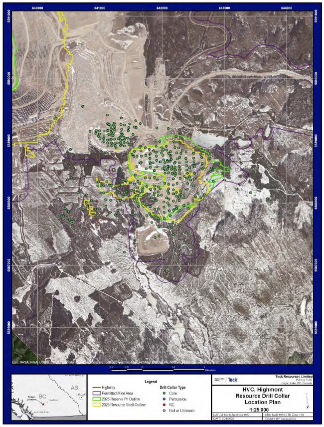
Figure 10-4: Drilling Used In Mineral Resource Estimation, Highmont Deposit
| October 2025 | Page 10- |
|
|
NI 43-101 Technical Report on Highland Valley Copper Operations British Columbia |
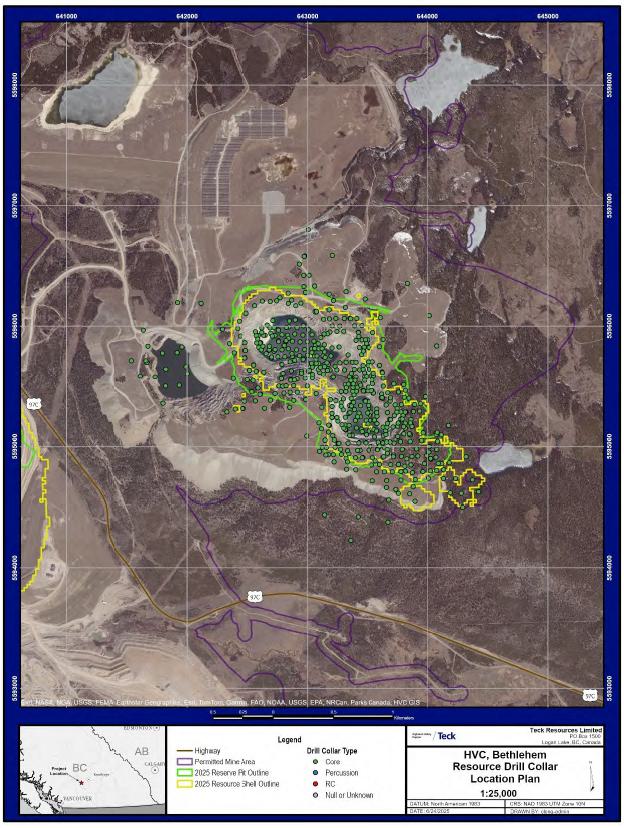
Figure 10-5: Drilling Used In Mineral Resource Estimation, Bethlehem Deposit
| October 2025 | Page 10- |
|
|
NI 43-101 Technical Report on Highland Valley Copper Operations British Columbia |
The Highland Valley Copper Partnership has engaged several third-party drilling contractors to conduct core drilling programs. Where known, the primary contractors and associated drill rig types include:
| · | SCS Diamond Drilling: using Boart Longyear LF90D drill rigs; |
| · | Foraco Canada Ltd. (Kamloops): using Atalier Val-d’Or VD-5000 drill rigs; |
| · | Geotech Drilling Services Ltd.: using Zinex A5 drill rigs. |
| 10.3 | Logging Procedures |
All modern drilling at Highland Valley Copper is conducted using core drilling methods. The exception was an RC drill program completed in the Lornex and Valley pits during 2015–2016.
RC Drilling (2015–2016)
RC chips were logged by geologists following Teck practices, and recorded mineralogy, alteration, and mineralization styles at 1.5 m intervals.
Core Drilling (2009–Report effective date)
Drill core is delivered to the core facility by the drilling contractor. Upon arrival, core is inspected by logging geologists or core technicians to assess recovery, quality, and cleanliness. The core is photographed wet photograph to document the core’s condition prior to any physical testing.
Geomechanical logging is performed by core technicians, followed by geological logging and sampling by geologists.
Logging intervals vary based on lithological, alteration, and mineralization variability, with a minimum sample length of 0.5 m. All significant structural features are recorded regardless of length. Specific gravity and point load tests are conducted approximately every 15 m downhole.
Sample intervals are defined by logging geologists, with lengths ranging from 0.5–3.0 m. Once sample tags are placed, the core is photographed dry.
| 10.4 | Recovery |
Systematic collection of drill core recovery data at Highland Valley Copper began in 2001. Prior to 2001, some core recovery data exist in the database but records are sporadic and incomplete.
Core recovery across all four deposit areas—Valley, Lornex, Highmont, and Bethlehem—has generally been acceptable, ranging from >88 to >94%. Intervals of low recovery are typically associated with fault zones, pre-mining surface exposure, or blast-related damage.
These recovery percentages are considered sufficient to support the geological interpretations and resource estimation for each deposit.
| October 2025 | Page 10- |
|
|
NI 43-101 Technical Report on Highland Valley Copper Operations British Columbia |
| 10.5 | Collar Surveys |
Documentation of drill collar survey methods and equipment prior to 2001 is not available, due to the lack of consistent record-keeping before the merger of Cominco Limited and Teck Corporation, which consolidated their interests in the Highland Valley Copper Partnership.
Legacy drill collar data were used in Mineral Resource estimation. In these instances, the legacy surveys were obtained from the original drill logs. The legacy collars were deemed valid because of the reconciliation performance observed over nearly four decades of mining operations at Highland Valley Copper Partnership and the Bethlehem legacy data study (see discussion in Section 12.3.2).
Collar survey methods included theodolites, and total station instruments. Current drill collar locations are typically located using high-precision GPS instruments. For angled drill holes, as-built surveys are conducted using total station instruments to ensure accurate collar orientation and positioning.
UAV photogrammetry is completed over the open pits, from which 3D photogrammetric maps of pit topography are generated. The UAV is also used to provide video footage for mine planning and pit inspections. Laser scanning is used for 3D mapping of pit walls, and to survey geotechnically sensitive areas.
| 10.6 | Downhole Surveys |
Documentation of downhole survey methods and equipment used prior to 2005 is limited due to inconsistent record-keeping. As a result, historical survey methodologies have not been compiled or entered into the acQuire database. However, legacy surveys were used in Mineral Resource estimation. Legacy surveys were obtained from the drill logs. The legacy survey data were deemed valid because of the reconciliation performance observed over nearly four decades of mining operations at Highland Valley Copper Partnership and the Bethlehem legacy data study (see discussion in Section 12.3.2).
Currently, downhole surveys are conducted using a Reflex single-shot survey tool. Surveys are typically performed at 60-m intervals on the way into the hole, at the end of the hole, and again at 60-m intervals on the way out, offset from the inbound survey depths where possible, or as permitted by ground conditions.
The Reflex tool records azimuth, dip, depth, roll (relative to dip), magnetic field strength, and temperature. Survey data are initially recorded by the driller on paper slips, which are then collected by the geologist. All measurements, excluding temperature, are reviewed and validated by a geologist before being uploaded into the acQuire database.
The acQuire software is used to apply a default validation threshold of a maximum deviation of 2.5° in dip and azimuth over 30 m. However, due to geological variability, this rule is not universally applicable, and survey data are also subject to visual validation by geological staff.
The current survey methodology and frequency are considered appropriate for the style of mineralization present at the Valley, Lornex, Highmont, and Bethlehem deposits.
| October 2025 | Page 10- |
|
|
NI 43-101 Technical Report on Highland Valley Copper Operations British Columbia |
| 10.7 | Grade Control |
Grade control at the Highland Valley Copper operations is managed through systematic blast hole drilling, which provides detailed spatial data to support ore-waste delineation and short-term mine planning.
Standardized drill patterns have been employed across the various deposits, with minor adjustments over time to optimize fragmentation, dilution control, and ore recovery. Blast hole patterns are summarized in Table 10-6.
The current blast hole drilling fleet consists of six Bucyrus 49R rotary drill rigs. These rigs are configured to drill standard production patterns using a hole diameter of 311 mm. For trim and buffer zones, a reduced hole diameter of 270 mm is employed to improve control near pit boundaries and minimize dilution.
| 10.8 | Sample Length/True Thickness |
The orientation and geometry of the porphyry systems vary across the different deposits, influencing drill hole design and sample length representativity (Table 10-7).
| 10.9 | Drilling Completed Since Database Close-out Date |
Since the database close-out dates for each of the Valley, Lornex, Highmont, and Bethlehem deposits (refer to Section 10.1), a total of 52 additional core holes, comprising 10,792 m, were completed as at 1 July, 2025.
The breakdown by area is as follows:
| · | Valley: 16 drill holes (4,526 m); |
| · | Lornex: 2 drill holes (651 m); |
| · | Bethlehem: 15 drill holes (2,679 m); |
| · | Highmont: 19 drill holes (2,936 m). |
The Qualified Person reviewed the available results from this drilling and compared them to the current block model. The comparison confirmed that the observed mineralization widths are consistent with those presented in the Mineral Resource estimate.
The 2025 drilling program commenced on 1 April, 2025. The objective of this program was to reduce geological and geometallurgical uncertainty related to copper distribution, copper recovery, and ore hardness, particularly in areas targeted for ore feed in the 5-Year Business Plan, which is part of the LOM plan. The program focused on the Valley, Lornex, Highmont, and Bethlehem deposits.
The 2025 program will include 65 planned drill holes totaling approximately 11,300 m. It incorporates a comprehensive geochemical and geometallurgical sampling and analysis component to meet Teck’s standards for sample density and data quality. As of the Report effective date, the QA/QC review of the geological logs and assay results from the 2025 program had not been completed.
| October 2025 | Page 10- |
|
|
NI 43-101 Technical Report on Highland Valley Copper Operations British Columbia |
Table 10-6: Blast Hole Patterns
| Deposit | Duration | Ore/Waste | Drill
Spacing (m) |
| Valley | Historical | Ore | 8.4 x 9.7 |
| Waste | 9.3 x 10.7 | ||
| Current (post 2019) | Ore | 6.4 x 7.4 | |
| Waste | 9.3 x 10.7 | ||
| Lornex | Historical | Ore and waste | 7.3 x 8.4 |
| Current (post 2019) | Ore and waste | 9.6 x 11 | |
| Highmont | Historical | Ore | 6.6 x 7.6 |
| Waste | 7.3 x 8.4 | ||
| Bethlehem | Not available | ||
Table 10-7: Drilled Versus True Thickness
| Deposit | Note |
| Valley (Centre) | Exhibits a structural trend striking at 315° with a dip of approximately 70° to the northeast and a plunge of 50° to the southeast. Drill sections have been established on a 65 m spacing along a southwest–northeast orientation. Drill holes completed prior to 2000 were predominantly vertical. Since 2001, most drill holes used for resource estimation have been inclined to better intersect the mineralized zones, except for geotechnical drill holes, which remain vertical. |
| Valley (Upper West Wall) | System trends at 240° and plunges vertically (90°). Drilling in this area has been conducted either perpendicular to the strike of the orebody or along strike, depending on the objective. Drill sections are variably spaced and oriented along both northwest–southeast and southwest–northeast directions. Most drill holes are inclined to optimize intersection angles with the mineralized structures. |
| Lornex | Strikes at 320°, dipping 70° to the southwest and plunging 75° to the southeast. Drill sections are spaced between 90–150 m along a west–east orientation. Most drill holes are inclined to intersect the mineralization at high angles. Vertical reverse circulation (RC) holes from the 2016 and 2025 campaigns are present but are located outside the current LOM plan and are not used in the resource estimate. |
| Highmont | Trends between 90° and 110° and is characterized by near-vertical dips. Drill sections are spaced between 50–100 m along a north–south orientation. Most drill holes are inclined and oriented north–south to intersect the mineralized zones effectively. A subset of east–west-oriented drill holes was designed to intersect the north–south-trending faults that traverse the deposit area. |
| Bethlehem | The Bethlehem porphyry systems, including the Jersey and Iona zones, are near-vertical in orientation. Drill sections are spaced at 40–50 m intervals along a west–east orientation. Most drill holes are inclined and designed to intersect the north–south-trending fault structures that influence mineralization distribution. |
| October 2025 | Page 10- |
|
|
NI 43-101 Technical Report on Highland Valley Copper Operations British Columbia |
| 10.10 | QP Comment on Item 10 “Drilling” |
There are no drilling, sampling, or recovery factors that could materially impact the accuracy and reliability of the results known to the QP.
Logging, recovery, and survey data collected during Teck’s drill programs are considered acceptable to support Mineral Resource and Mineral Reserve estimation and can support mine planning.
Historical data are accepted for estimation support based on the reconciliation performance observed over nearly four decades of mining operations (see Section 12.3.2).
| October 2025 | Page 10- |
|
|
NI 43-101 Technical Report on Highland Valley Copper Operations British Columbia |
| 11 | SAMPLE PREPARATION, ANALYSES, AND SECURITY |
| 11.1 | Sample Methods |
| 11.1.1 | GEOCHEMICAL SAMPLING |
Geochemical sampling was completed as part of regional exploration and scientific studies. These samples do not support Mineral Resource estimation.
| 11.1.2 | REVERSE CIRCULATION DRILL SAMPLING |
During the 2015–2016 RC program, primary samples were collected on continuous 1.5 m intervals. Samples were split, with 7 kg of primary sample placed in micro-pore bags with barcoded tags. Coarse rejects were collected in larger bags and similarly labeled. Each sample was assigned a unique ID, with QA/QC samples inserted per a pre-generated list from the acQuire database. Weights of both primary and reject samples were recorded. Cleaning of cyclone and splitter were performed between samples using compressed air (dry) or water (wet).
Representative chips were collected for geological logging and stored in chip trays.
Samples and rejects were stored at the drill site and transported to the core shack at the end of each shift for batch preparation. Sample bags were placed into large apple crates, sealed with metal banding, and prepared for shipment. Crates were transported to the analytical laboratory by a third-party carrier. Upon arrival, laboratory staff inventoried the samples and confirmed receipt.
| 11.1.3 | CORE SAMPLING |
Core sampling procedures evolved over time, reflecting advancements in sampling methodology, analytical standards, and quality assurance protocol. These procedures were applied across the Valley, Lornex, Highmont, and Bethlehem deposits.
| 11.1.3.1 | Historical Core Sampling (pre-2010) |
Historical core sampling was conducted using a combination of whole core and split core methods, depending on the time and operational practices in place. In earlier programs, core was commonly sampled as whole core at 3 m intervals, particularly during initial exploration and development phases. As practices improved, manual core splitters were introduced, and core was routinely split in half, with one half submitted for analysis and the other retained for reference.
Documentation of sampling protocols, and QA/QC procedures from this period is limited. However, subsequent validation efforts, including twin drilling (Bethlehem 2012 drill program) and re-assaying of archived material, were undertaken to assess the reliability of historical data, and support its integration into the current geological models.
| October 2025 | Page 11- |
|
|
NI 43-101 Technical Report on Highland Valley Copper Operations British Columbia |
| 11.1.3.2 | Modern Core Sampling (post-2010) |
Core sampling procedures were standardized in 2010, ensuring consistency, data integrity, and traceability.
From 2010–2014, drill core was halved using a combination of manual and hydraulic core splitters. Beginning in 2014, the operations transitioned to using core saws to improve precision and reduce the potential for sample loss or contamination. In all cases, the ‘A’ half of the core is submitted for geochemical analysis, while the ‘B’ half is retained in the core box for future reference, re-sampling, or quality assurance and quality control (QA/QC) purposes.
Sample intervals vary by core diameter. NQ-diameter core is sampled at 3 m intervals, and HQ-diameter core is sampled at 2 m intervals.
After sampling, sample bags are placed into large apple crates, sealed with metal banding, and prepared for shipment. Crates are transported to the analytical laboratory by a third-party carrier. Upon arrival, laboratory staff inventory the samples and confirm receipt.
In the QP’s opinion, these procedures ensure high-quality, representative sampling across all core drilling programs, and the resulting samples support Mineral Resource estimation.
| 11.1.4 | BLAST HOLE SAMPLING |
Blast hole drilling is conducted exclusively to support active mining operations, and is also used in Mineral Resource estimation domain modeling, except for the Bethlehem deposit. Blast hole samples are integral to the construction of ore control models, which guide material classification during mining.
Blast hole samples are routinely collected by drill operators following internal written protocols. The procedure is as follows:
| · | At each designated blast hole location, the driller places a sample bag into a collection cup, folding the top of the bag over the cup’s rim. The cup is then positioned in the sample catcher and lowered through an opening in the drill platform to align with the drill hole; |
| · | Sub-drill cuttings are included in the sample, eliminating the need to interrupt drilling for sample collection. Upon hole completion, the sample catcher is raised, and the bag is retrieved; |
| · | Each sample bag should be at least half full. If underfilled (less than one-quarter full), additional cuttings are collected manually from the cutting pile, ensuring a representative vertical profile; |
| · | Sampling frequency varies by material type: |
| o | At ore/waste contacts: every blast hole is sampled; |
| o | In solid ore zones: every second hole is sampled; |
| o | In solid waste zones: every tenth hole is sampled. |
All grade control drilling is conducted under the supervision of the mine operations and geology teams to ensure alignment with production schedules and ore control protocols. Blast hole samples are routinely collected and analyzed to inform short-term block models and guide ore routing decisions. While blast hole data are critical for operational decision-making, they were also incorporated into creating grade domains during Mineral Resource estimation, for all deposits except the Bethlehem deposit.
| October 2025 | Page 11- |
|
|
NI 43-101 Technical Report on Highland Valley Copper Operations British Columbia |
| 11.2 | Density Determinations |
No historical specific gravity (SG) measurements pre-dating 2010 were identified in the current database. SG data collection commenced in 2010 and continued through 2019 across the four deposit areas. SG measurements are being taken during the drill program that is in in progress at the Report effective date.
Specific gravity measurements were, and continue to be, routinely collected from drill core at approximately 15 m intervals. Samples are typically 10–20 cm in length and selected to avoid visible fractures, thereby ensuring sample integrity during weighing. This selection process introduces a bias toward more competent, intact rock, and may under-represent faulted, highly fractured, or unconsolidated material.
SG determinations are performed by core logging personnel at the Teck core facility using the water displacement method. Fractured or clay-rich samples are excluded due to their tendency to disintegrate during immersion.
The specific gravity is calculated using the formula:
| · | Specific gravity = dry weight (g) ÷ [dry weight (g) – wet weight (g)]. |
To ensure data quality, a stainless-steel standard is included with each batch of measurements for calibration and verification.
Results are summarized in Table 11-1.
| 11.3 | Analytical and Test Laboratories |
A number of analytical and test laboratories have been used over time. Where known, they are summarized in Table 11-2, and their accreditations and independence status are also provided that table.
There have been two main primary analytical laboratories that provided analytical services, the Highland Valley Copper Operations mine laboratory (the mine laboratory) and the laboratory currently known as Bureau Veritas Commodities Vancouver (Bureau Veritas). ACME Analytical Services (ACME) acted as the check assay laboratory for the mine laboratory. The ALS laboratory in North Vancouver (ALS) is the check assay laboratory for Bureau Veritas.
From 2014 the primary analytical laboratory processing drill core samples was switched to ACME. ACME had been acquired by Bureau Veritas in 2011; however, their integration into the wider Bureau Veritas group took several years. During this time data was reported as from ACME though they were Bureau Veritas at this time. Teck has used ACME/Bureau Veritas as the primary analytical laboratory for drill core material from 2014 to present. The names of the analytical methods used at ACME changed on transition to Bureau Veritas; however, the actual analytical methods and underlying sample decompositions did not change e.g., ACME 7TD2 is the exact same as Bureau Veritas MA370.
When Bureau Veritas/ACME became the primary analytical laboratory, the check samples were sent to ALS.
| October 2025 | Page 11- |
|
|
NI 43-101 Technical Report on Highland Valley Copper Operations British Columbia |
Table 11-1: Specific Gravity Summary Table
| Deposit | Unit | Specific Gravity | Note | |
| Mean | Range | |||
| Valley | All available samples | 2.64 | 1.85–3.24 | Dominated by Bethsaida granodiorite (BGD) lithologies |
| For: Avalanche | 2.45 | 1.85-3.13 | ||
| For: Overburden units | 2.43 | 1.85-3.13 | Unmineralized units | |
| Lornex | All Available Samples | 2.62 | 2.20–2.92 | Dominated by Skeena (SKN) lithologies |
| For: Bethsaida granodiorite (west of Lornex fault, unmineralized) | 2.60 | 2.20-2.92 | ||
| Highmont | All available samples | 2.60 | 2.36–2.98 | Dominated by Skeena (SKN) lithologies |
| Bethlehem | All available samples | 2.67 | 2.00–3.00 | Dominated by Bethlehem (BETH) lithologies |
Table 11-2: Analytical and Test Laboratories
| Laboratory | Years Used | Purpose | Accreditation | Independent |
| Highland Valley Copper mine laboratory | 1960s–2013 | Primary analytical laboratory analysing a variety of sample types including blasthole, core, RC. | None | Not independent |
| ACME Analytical Vancouver | Pre-2014 | Check laboratory for mine laboratory | ISO9001, ISO/IEC17025 | Independent |
| ACME Analytical Vancouver | 2014–2017 | Primary analytical lab for drilling samples | ISO9001, ISO/IEC17025 | Independent |
| Bureau Veritas Commodities Vancouver | 2017–2025 | Primary analytical laboratory for drilling samples | ISO9001, ISO/IEC17025 | Independent |
| ALS North Vancouver | 2014–2025 | Check laboratory | ISO/IEC17025 | Independent |
| 11.4 | Sample Preparation |
Sample preparation methods had minor variations between the different laboratories (Table 11-3).
The sample preparation methods used are generally consistent. Review of crush, pulp and field/core duplicate quality samples supports the conclusion that the sample preparation processes employed are fit for purpose. Where QC control failures have occurred, they are usually due to resolvable sample swaps.
| October 2025 | Page 11- |
|
|
NI 43-101 Technical Report on Highland Valley Copper Operations British Columbia |
Table 11-3: Sample Preparation Methods
| Laboratory | Years Used | Sample Preparation Method |
| Highland Valley Copper mine laboratory | Historic–2013 | Crush the entire sample with jaw crushers to 95% passing 3.35mm, pulverize using ring mill and puck to 95% passing 106 µm (150 mesh). |
| ACME Analytical/Bureau Veritas Vancouver | 2014–2025 | Crush entire sample with jaw crushers to 70% passing 2 mm, pulverize using ring mill and puck to 85% passing 75 µm (200 mesh). |
| 11.5 | Analysis |
Analytical methods varied by laboratory and are summarized in Table 11-4. Detection limits are provided in Table 11-5.
Current analytical methods used at Bureau Veritas include MA370, MA200, TC000, TC008, LH402 and LH403.
Methods used at ALS include ME-MS61, ME-OG62, ME-IR08, Cu-AA05 and CuAA17.
Methods ME-MS61 and ME-OG62 are equivalent to Bureau Veritas methods MA200 and MA370, respectively.
ALS method ME-IR08 is equivalent to Bureau Veritas method TC000.
ALS methods Cu-AA05 and Cu-AA17 are equivalent to Bureau Veritas methods LH402 and LH403.
| 11.6 | Quality Assurance and Quality Control |
A formal QA/QC sample insertion protocol was implemented in 2016, based on recommendations by industry experts and updated in 2022 to align with Teck’s internal geochemistry QA/QC protocols. The program applies to both core and RC drilling, and includes different quality control measures.
Standard reference materials (standards), coarse and pulp blanks, and duplicates are inserted into the sample stream using the insertion rates summarized in Table 11-6.
Check (umpire) samples are preselected by Teck staff. After analysis is completed at Bureau Veritas and has passed batch-level quality control, the samples are sent directly to ALS, typically, either at the end of a field program or annually for ongoing drilling. Check assay results are evaluated using a combination of quantile–quantile plots, duplicate min–max plots and reduced major axis plots.
Third-party laboratories such as ALS and Bureau Veritas insert their own quality controls. While this is good practice and part of their accreditation process, Teck does not assess these quality controls as they are not blind to the laboratory.
| October 2025 | Page 11- |
|
|
NI 43-101 Technical Report on Highland Valley Copper Operations British Columbia |
Table 11-4: Analytical Methods at Laboratories Used
| Laboratory | Years Used |
Method Name and Description |
Analytical Digest | Analytical Finish |
| Mine laboratory | Historic-2013 | Aqua regia leach with AAS analytical finish (Cu, Mo, As, Fe) | Aqua regia | Atomic Absorption Spectroscopy |
| ACME | Pre-2014 | 7TD2. Multi acid digestion reporting suite of elements | 4-acid digestion | ICP-AES |
| 1DX1. Aqua regia digestion reporting suite of elements | Aqua regia | ICP-AES and ICP-MS | ||
| Bureau Veritas | 2014–2025 | MA200. Multi acid digestion reporting suite of elements | 4-acid digestion | ICP-AES and ICP-MS |
| AQ200. Aqua regia digestion reporting suite of elements | Aqua regia | ICP-AES and ICP-MS | ||
| MA370. Multi acid digestion reporting suite of elements | 4-acid digestion | ICP-AES | ||
| TC000. Infrared combustion method reporting S and C | None | Infrared combustion | ||
| TC008. Sample is pre-ignited at 600oC, the remaining residue is analysed by infrared combustion and reported as SO4 | Sample is pre-ignited at 600oC, residual S is analysed | Infrared combustion | ||
| LH402. 5% sulphuric acid leach reporting Cu oxides | 5% H2SO4 leach | AAS | ||
| LH403 . 1% NaCN leach reporting Cu oxides and secondary sulphides | 1% NaCN leach | AAS | ||
| ALS | 2014–2025 | ME-MS61. Multi acid digestion reporting suite of elements | 4-acid digestion | ICP-AES and ICP-MS |
| ME-OG62. Multi acid digestion reporting suite of elements. Requested where Cu >1,000 ppm by ME-MS61 or Mo >500 ppm | 4-acid digestion | ICP-AES | ||
| C-IR07. Infrared combustion method reporting C | None | Infrared combustion | ||
| S-IR08. Infrared combustion method reporting S | None | Infrared combustion | ||
| Cu-AA05. 5% H2SO4 leach reporting Cu | 5% H2SO4 leach | AAS | ||
| Cu-AA17. 1% NaCN leach reporting Cu | 1% NaCN leach | AAS |
| October 2025 | Page 11- |
|
|
NI 43-101 Technical Report on Highland Valley Copper Operations British Columbia |
Table 11-5: Analytical Methods Reported Elements and Detection Limits
| Laboratory | Analytical Method |
Analyte | Detection Limit |
Analyte | Detection Limit |
| Mine laboratory | Aqua regia leach | Cu | unknown | As | unknown |
| Mo | unknown | Fe | unknown | ||
| ACME | 7TD2 | Ag | 2 ppm | Mn | 0.01% |
| Al | 0.01% | Mo | 0.001% | ||
| As | 0.02% | Na | 0.01% | ||
| Bi | 0.01% | Ni | 0.001% | ||
| Ca | 0.01% | P | 0.01% | ||
| Cd | 0.001% | Pb | 0.02% | ||
| Co | 0.001% | Rb | 0.5 ppm | ||
| Cr | 0.001% | S | 0.05% | ||
| Cu | 0.001% | Sb | 0.01% | ||
| Fe | 0.01% | Sr | 0.01% | ||
| K | 0.01% | W | 0.01% | ||
| Mg | 0.01% | Zn | 0.01% | ||
| 1DX1 | Ag | 0.1 ppm | Mn | 1% | |
| Al | 0.01% | Mo | 0.1 ppm | ||
| As | 0.5 ppm | Na | 0.001% | ||
| Au | 0.5 ppb | Ni | 0.1 ppm | ||
| B | 20 ppm | P | 0.001% | ||
| Ba | 1 ppm | Pb | 0.1 ppm | ||
| Bi | 0.1 ppm | S | 0.05% | ||
| Ca | 0.01% | Sb | 0.1 ppm | ||
| Cd | 0.1 ppm | Sc | 0.1 ppm | ||
| Co | 0.1 ppm | Se | 0.5 ppm | ||
| Cr | 1 ppm | Sr | 1 ppm | ||
| Cu | 0.1 ppm | Te | 0.2 ppm | ||
| Fe | 0.01% | Th | 0.1 ppm | ||
| Ga | 1 ppm | Ti | 0.001% | ||
| Hg | 0.01 ppm | Tl | 0.1 ppm | ||
| K | 0.01% | V | 2 ppm | ||
| La | 1 ppm | W | 0.1 ppm | ||
| Mg | 0.01% | Zn | 1 ppm |
| October 2025 | Page 11- |
|
|
NI 43-101 Technical Report on Highland Valley Copper Operations British Columbia |
| Laboratory | Analytical Method |
Analyte | Detection Limit |
Analyte | Detection Limit |
| BV Vancouver | MA200 | Ag | 0.1 ppm | Ni | 0.1 ppm |
| Al | 0.01% | P | 0.001% | ||
| As | 1 ppm | Pb | 0.1 ppm | ||
| Ba | 1 ppm | Rb | 0.1 ppm | ||
| Be | 1 ppm | Re | 0.005 ppm | ||
| Bi | 0.1 ppm | S | 0.1% | ||
| Ca | 0.01% | Sb | 0.1 ppm | ||
| Cd | 0.1 ppm | Sc | 1 ppm | ||
| Ce | 1 ppm | Se | 1 ppm | ||
| Co | 0.2 ppm | Sn | 0.1 ppm | ||
| Cr | 1 ppm | Sr | 1 ppm | ||
| Cu | 0.1 ppm | Ta | 0.1 ppm | ||
| Fe | 0.01% | Te | 0.5 ppm | ||
| Hf | 0.1 ppm | Th | 0.1 ppm | ||
| In | 0.05 ppm | Ti | 0.001% | ||
| K | 0.01% | Tl | 0.5 ppm | ||
| La | 0.1 ppm | U | 0.1 ppm | ||
| Li | 0.1 ppm | V | 4 ppm | ||
| Mg | 0.01% | W | 0.1 ppm | ||
| Mn | 1 ppm | Y | 0.1 ppm | ||
| Mo | 0.1 ppm | Zn | 1 ppm | ||
| Na | 0.001% | Zr | 0.1 ppm | ||
| Nb | 0.1 ppm | ||||
| MA370 | Ag | 2 ppm | Mn | 0.01% | |
| Al | 0.01% | Mo | 0.001% | ||
| As | 0.02% | Na | 0.01% | ||
| Bi | 0.01% | Ni | 0.001% | ||
| Ca | 0.01% | P | 0.01% | ||
| Cd | 0.001% | Pb | 0.02% | ||
| Co | 0.001% | S | 0.05% | ||
| Cr | 0.001% | Sb | 0.01% | ||
| Cu | 0.001% | Sr | 0.01% | ||
| Fe | 0.01% | W | 0.01% | ||
| K | 0.01% | Zn | 0.01% | ||
| Mg | 0.01% |
| October 2025 | Page 11- |
|
|
NI 43-101 Technical Report on Highland Valley Copper Operations British Columbia |
| Laboratory | Analytical Method |
Analyte | Detection Limit |
Analyte | Detection Limit |
| AQ200 | Ag | 0.1 ppm | Mo | 0.1 ppm | |
| Al | 0.01% | Na | 0.001% | ||
| As | 0.5 ppm | Ni | 0.1 ppm | ||
| Au | 0.5 ppb | P | 0.001% | ||
| B | 20 ppm | Pb | 0.1 ppm | ||
| Ba | 1 ppm | S | 0.05% | ||
| Bi | 0.1 ppm | Sb | 0.1 ppm | ||
| Ca | 0.01% | Sc | 0.1 ppm | ||
| Cd | 0.1 ppm | Se | 0.5 ppm | ||
| Co | 0.1 ppm | Sr | 1 ppm | ||
| Cr | 1 ppm | Te | 0.2 ppm | ||
| Cu | 0.1 ppm | Th | 0.1 ppm | ||
| Fe | 0.01% | Ti | 0.001% | ||
| Ga | 1 ppm | Tl | 0.1 ppm | ||
| Hg | 0.01 ppm | U | 0.1 ppm | ||
| K | 0.01% | V | 1 ppm | ||
| La | 1 ppm | W | 0.1 ppm | ||
| Mg | 0.01% | Zn | 1 ppm | ||
| Mn | 1 ppm | ||||
| TC000 | TotS (total sulphur) | 0.02% | TotC (Total Carbon) | 0.02% | |
| TC008 | SO4 | 0.05% | — | — | |
| LH402 | CuS (5% sulphuric acid leachable copper) | 0.001% | — | — | |
| LH403 | CuCN (1% NaCN leachable Cu) | 0.01% | — | — |
| October 2025 | Page 11- |
|
|
NI 43-101 Technical Report on Highland Valley Copper Operations British Columbia |
| Laboratory | Analytical Method |
Analyte | Detection Limit |
Analyte | Detection Limit |
| ALS Vancouver | ME-MS61 | Ag | 0.01 ppm | Na | 0.01% |
| Al | 0.01% | Nb | 0.1 ppm | ||
| As | 0.2 ppm | Ni | 0.2 ppm | ||
| Ba | 10 ppm | P | 10 ppm | ||
| Be | 0.05 ppm | Pb | 0.5 ppm | ||
| Bi | 0.01 ppm | Rb | 0.1 ppm | ||
| Ca | 0.01% | Re | 0.002 ppm | ||
| Cd | 0.02 ppm | S | 0.01% | ||
| Ce | 0.01 ppm | Sb | 0.05 ppm | ||
| Co | 0.1 ppm | Sc | 0.1 ppm | ||
| Cr | 1 ppm | Se | 1 ppm | ||
| Cs | 0.05 ppm | Sn | 0.2 ppm | ||
| Cu | 0.2 ppm | Sr | 0.2 ppm | ||
| Fe | 0.01% | Ta | 0.05 ppm | ||
| Ga | 0.05 ppm | Te | 0.05 ppm | ||
| Ge | 0.05 ppm | Th | 0.01 ppm | ||
| Hf | 0.1 ppm | Ti | 0.005% | ||
| In | 0.005 ppm | Tl | 0.02 ppm | ||
| K | 0.01% | U | 0.1 ppm | ||
| La | 0.5 ppm | V | 1 ppm | ||
| Li | 0.2 ppm | W | 0.1 ppm | ||
| Mg | 0.01% | Y | 0.1 ppm | ||
| Mn | 5 ppm | Zn | 2 ppm | ||
| Mo | 0.05 ppm | Zr | 0.5 ppm | ||
| ME-OG62 | Ag | 1 ppm | Mg | 0.01% | |
| As | 0.001% | Mn | 0.01% | ||
| Bi | 0.001% | Mo | 0.001% | ||
| Cd | 0.001% | Ni | 0.001% | ||
| Co | 0.0005% | Pb | 0.001% | ||
| Cr | 0.002% | S | 0.01% | ||
| Cu | 0.001% | Zn | 0.001% | ||
| Fe | 0.01% | ||||
| Cu-AA05 | CuS (5% Sulphuric acid leachable Cu) | 0.001% | — | — | |
| Cu-AA17 | CuCN (1%NaCN leachable Cu) | 0.001% | — | — | |
| C-IR07 | TotC (Total Carbon) | 0.01% | — | — | |
| S-IR08 | TotS (Total Sulphur) | 0.01% | — | — |
| October 2025 | Page 11- |
|
|
NI 43-101 Technical Report on Highland Valley Copper Operations British Columbia |
Table 11-6: Control Sample Insertion Rates
| Sample Type | Insertion Frequency (%) |
| Twin samples | 3 |
| Coarse duplicates* | 2 |
| Coarse blanks | 3 |
| Pulp duplicates* | 2 |
| Standards | 5 |
| Fine blanks | 2 |
| Check samples** | 5 |
* Assayed by the primary laboratory: ** Assayed by the secondary laboratory; included additional control samples (pulp duplicates, standards, and fine blanks)
Data are imported into the acQuire database on receipt. Each batch of received data is evaluated using QA/QC modules within acQuire as per Teck’s internal geochemistry QA/QC protocols. Evaluations focus on key analytes, particularly copper and molybdenum, at both trace and ore-grade levels. If data are deemed acceptable, the data are accepted within acQuire and become available for use. Data that have not been accepted is not available for use. Records of these batch level assessments are retained.
Where a quality control sample is outside allowed tolerances, it is reviewed by a quality control specialist who may recommend re-assays and/or other remedial actions.
At the end of each major drilling campaign or annually an overall quality control report is generated evaluating standard, blank and duplicate sample performance across the season. This quality control report helps identify more subtle analytical trends that may not be apparent during batch level quality control reviews.
| 11.7 | Databases |
Historical geological and drilling data collected prior to 1997 were originally recorded on paper and maintained under the custody of the mine’s geological department. In 1998, these records were digitized and transferred into a Microsoft Access database, which was subsequently migrated to a Microsoft SQL Server environment.
The current centralized geological database was established in 2013. It is a relational database hosted on a secure server, using Microsoft SQL Server and managed through the acQuire data management system. The database structure includes key data domains such as collar, downhole survey, lithology, sample dispatch, primary assays, and check assays.
Geological logging data is either logged directly withing the acQuire database or exported directly from the current logging software, validated, and then imported into the acQuire database. Once analytical results have passed QA/QC protocols, they are integrated with the logging data and linked to Leapfrog GEO software. This integration supports the generation of geochemical and geological strip logs and serves as the foundation for the development and updating of geoscientific models.
| October 2025 | Page 11- |
|
|
NI 43-101 Technical Report on Highland Valley Copper Operations British Columbia |
The database is maintained onsite by the SP geology team, with oversight provided by a Senior Data Specialist based at Teck’s Vancouver Head Office. Regular backups are performed in accordance with Teck’s corporate data management protocols to ensure data security and integrity.
| 11.8 | Sample Security |
Due to multiple changes in ownership and consolidation of operations, there is no documented information available regarding sample security protocols at the Highland Valley Copper Operations prior to 2004.
Since 2004, when Teck Cominco became the sole operator, sample security measures have been standardized and consistently applied. From 2004–2013, Teck personnel were responsible for preparing samples for transport and maintaining detailed records of each shipment. During this period, all samples remained under Teck’s custody on company property, supervised by the Senior Mine Geologist, until delivery to the on-site laboratory for preparation and analysis. Upon arrival, samples were verified by laboratory staff, and any discrepancies were promptly reported to the Geology department.
Currently, Teck staff continue to oversee sample preparation and shipment to the independent Bureau Veritas laboratory in Vancouver. Chain-of-custody protocols are strictly followed, including the completion of sample submittal forms that accompany each shipment to ensure full accountability and traceability.
No significant sample security issues have been identified since the implementation of these procedures.
| 11.9 | Sample Storage |
Historical drill core collected between the 1960s and 2008 is no longer intact, having been either discarded or degraded due to prolonged exposure to environmental conditions. Similarly, pulps and coarse rejects generated between the 1960s and 2013 were disposed of by various on-site and external laboratories over time.
From 2009 onward, drill core has been handled using standardized procedures. Upon completion of sampling, core is placed in wooden box trays, each marked with a metal identification tag. These trays are stacked on wooden pallets and stored outdoors adjacent to the core facility. Due to exposure to high-altitude weather conditions, some degree of core degradation over time is expected.
Pulps and coarse rejects generated from 2014 to the present are returned to site by Bureau Veritas. These materials are stored in secure shipping containers located next to the core facility.
| 11.10 | QP Comment on Item 11 “Sample Preparation, Analyses and Security” |
In the opinion of the QP, the sampling, sample preparation, analytical methods, and quality control procedures employed during data collection programs completed by the Highland Valley Copper Partnership are appropriate for the estimation of Mineral Resources and Mineral Reserves and are suitable for use in mine planning.
| October 2025 | Page 11- |
|
|
NI 43-101 Technical Report on Highland Valley Copper Operations British Columbia |
This conclusion is based on the following observations:
| · | Core handling and sample collection procedures adhere to industry-standard practices, with protocols in place to minimize sample loss and reduce potential sampling bias; |
| · | Sample preparation techniques are consistent with accepted industry norms and are appropriate for the style and characteristics of the mineralization; |
| · | Analytical methods employed are standard within the industry and are suitable for the mineralization type under investigation; |
| · | QA/QC protocols have been in place since 2003. Control sample insertion rates are consistent with industry expectations, and no material analytical biases have been identified through QA/QC data reviews; |
| · | Bulk density determination procedures follow industry-standard methodologies. The number and quality of determinations are sufficient to support the tonnage estimates for waste, oxide, and sulphide mineralization; |
| · | Data validation protocols are embedded within the database system, including automated checks during data upload. These validation measures are appropriate and align with industry best practices; |
| · | Sample security protocols are considered adequate and consistent with standard industry practices; |
| · | Current sample storage procedures and facilities meet industry standards and are deemed appropriate for long-term data integrity. |
Data verification that allowed the Qualified Person to incorporate drill and analytical data collected prior to 2003 is discussed in Section 12.
| October 2025 | Page 11- |
|
|
NI 43-101 Technical Report on Highland Valley Copper Operations British Columbia |
12 DATA VERIFICATION
12.1 Internal Data Verification
| 12.1.1 | DATA VERIFICATION AND QUALITY ASSURANCE |
Highland Valley Copper personnel prepare an annual “Resource and Reserve” report that documents the methodologies and data supporting the Mineral Resource and Mineral Reserve estimates for the reporting year. The report is prepared under Teck’s internal governance framework, incorporates site visits and peer reviews, and is formally signed off by Qualified Persons. The report includes a comprehensive review of the following components:
| · | Internal validation procedures are applied during data entry to ensure consistency between lithology, assay grades, downhole surveys, and core recovery records and the geological database; |
| · | QA/QC data are rigorously reviewed and approved prior to the inclusion of analytical results in the database; |
| · | Inputs, methodologies, parameters, and outputs related to geological modeling and domain definition are reviewed and validated prior to resource estimation; |
| · | Reconciliation analyses to assess the alignment between model predictions and actual production outcomes. |
No material issues were identified during these reviews that would adversely impact the reliability of the Mineral Resource or Mineral Reserve estimates.
| 12.1.2 | PROCESS AUDITS AND INDEPENDENT REVIEWS |
Teck personnel have conducted site visits to analytical laboratories to observe and assess sample preparation and analytical procedures.
In addition, Teck’s Reserve Evaluation Group performs an annual audit of each operation, including the Highland Valley Copper Operations. These audits evaluate adherence to corporate standards for data acquisition, verification, and estimation practices. The reviews also assess the outcomes of these processes. No material deficiencies were identified during these audits that would affect the Mineral Resource or Mineral Reserve estimates.
| 12.2 | External Data Verification |
Numerous external audits or data collection supervision have been undertaken since 2004, as summarized in Table 12-1.
These audits indicated no material deficiencies resulting from the information that was audited.
| October 2025 | Page 12- |
|
|
NI 43-101 Technical Report on Highland Valley Copper Operations British Columbia |
Table 12-1: External Data Verification
| Year | Company | Work Undertaken |
| 2004 | AMEC | Design and supervision of QC program |
| 2005–2008 | AMEC | Design and supervision of QC program |
| CRM SA | Audit of QC program | |
| 2010–2011 | AMEC | Design and supervision of QC program |
| CRM SA | Audit of QC program | |
| 2011–2012 | AMEC | Design and supervision of QC program |
| Golder Associates | Audit of QC program | |
| 2012–2016 | Amec Foster Wheeler | Design and supervision of QC program |
| Geosystem International Inc. | Audit of QC program | |
| 2017–2021 | SRK Consulting (Canada) Inc. | Audit of QC program |
| 2020 | CSA Global Pty. Ltd. | Audited mine plan and Mineral Resource and Reserve estimates |
| 2025 | SRK Consulting (Canada) Inc. | Audited mine plan and Mineral Resource and Reserve estimates |
12.3 Verification by Qualified Persons
| 12.3.1 | MR. CHRISTOPHER HERCUN |
Mr. Hercun works at the Highland Valley Copper Operations as described in Section 2.4.1.
Mr. Hercun conducted a comprehensive review of the following components:
| · | Operational inputs used in mine planning, including availability and productivity assumptions, and geological and geo-metallurgical models; |
| · | Economic inputs and model used for financial modelling, including marketing, commodity price, revenue, and cost assumptions; |
| · | Permitting, infrastructure and tenure requirements to enable execution of the mine plans described in this Report; |
| · | Environmental, social and closure considerations associated with the LOM plan; |
| · | Risks and opportunities associated with the LOM plan. |
In the QP’s opinion, the completed verification supports the assumptions used in the Mineral Resource and Mineral Reserve estimates and the financial analysis that supports the Mineral Reserve estimates.
| 12.3.2 | MR. ALEX STEWART |
Mr. Stewart works at the Highland Valley Copper Operations as described in Section 2.4.2.
| October 2025 | Page 12- |
|
|
NI 43-101 Technical Report on Highland Valley Copper Operations British Columbia |
Mr. Stewart conducted a comprehensive review of the following components:
| · | Bethlehem legacy data were evaluated. The 1970s and 1980s (refer to Table 10-5) drill data showed a reasonable correlation with modern assay results and were therefore considered suitable for inclusion in grade estimation. In contrast, the B-series data from 1955–1969 drilling (see mention in Table 10-1) were found to be erratic and systematically biased, leading to its exclusion from grade estimation. However, due to its extensive coverage in areas with limited modern data, the B-series drilling was still used to support geological modeling and to help define the shapes of mineralized domains; |
| · | Highmont, Lornex and Valley legacy data were deemed valid. Reconciliation performance has been observed over nearly four decades of mining operations at Highland Valley Copper Partnership. From 1986–2025, reconciliation data from the Valley, Lornex, and Highmont pit, each mined at varying rates over the year, demonstrate a high degree of consistency between resource model predictions and actual mill performance. Over this 38-year period, the resource models have shown a strong correlation with production outcomes, with tonnage over-predicted by only 0.38%, and copper and molybdenum grades under-predicted by just 0.93% (copper grade difference 0.004%) and 13.85% (molybdenum grade difference 0.0012%), respectively. These variances fall well within acceptable industry standards and indicate a high level of confidence in the predictive accuracy of the models and the reliability of the underlying data. This long-term reconciliation success provides compelling empirical validation for the reliability of the legacy drilling data incorporated into the models, despite the inherent limitations of older datasets, such as incomplete documentation or less rigorous QA/QC protocols compared to today’s standards. Their inclusion has not compromised the overall accuracy of the resource estimates. Instead, the consistency between modeled and actual production results over such an extended period underscores the robustness of the geological interpretations and supports the continued use of legacy data in resource estimation; |
| · | Current core drilling data collection methodologies, including logging, sampling, and core handling procedures; |
| · | Current data entry and upload protocols to the geological database; |
| · | Historical and current QA/QC programs, including the assessment of control sample performance; |
| · | Current inputs, methodologies, parameters, and outputs used in the development of estimation domains and resource models; |
| · | Current reconciliation analyses comparing production data to model predictions. |
In addition, Mr. Stewart reviewed the outcomes of independent audits and technical reviews as part of the data verification process.
Based on these evaluations, it is the QP’s opinion that the data verification procedures are adequate, and that the data are suitable for use in the preparation of the Mineral Resource estimate.
| October 2025 | Page 12- |
|
|
NI 43-101 Technical Report on Highland Valley Copper Operations British Columbia |
| 12.3.3 | MR. TIM TSUJI |
Mr. Tsuji works at the Highland Valley Copper Operations as described in Section 2.4.3.
Mr. Tsuji conducted a comprehensive review of the following components:
| · | Pit and WRSF designs and the application of geotechnical criterial to those designs; |
| · | Mining equipment requirements and production rates; |
| · | Cut-off grade selection; |
| · | Pit optimization parameters. |
Based on these reviews, it is the QP’s opinion that the Mineral Resource pit shells and the Mineral Reserves mine plan are supported.
| 12.3.4 | MR. FRANK LAROCHE |
Mr. Laroche works at the Highland Valley Copper Operations as described in Section 2.4.4.
Mr. Laroche conducted a comprehensive review of the following components:
| · | Assessment of the methodologies employed in the development of the 2025 annual planning cycle copper recovery model; |
| · | Evaluation of the methodologies used to construct concentrate grade models; |
| · | Review of the approaches applied in the development of molybdenum recovery models; |
| · | Assessments of the methodologies used to collect geometallurgical data for development of the mine life recovery and throughput model; |
| · | On-site inspections of processing circuits, including crushing, grinding, flotation, and dewatering operations; |
| · | Reconciliation of the current throughput and the recovery models. |
In the QP’s opinion, the completed verification supports the use of the metallurgical and process data and supporting assumptions in Mineral Resource and Mineral Reserve estimation and in the economic analysis that supports the Mineral Reserves.
| October 2025 | Page 12- |
|
|
NI 43-101 Technical Report on Highland Valley Copper Operations British Columbia |
| 12.3.5 | MR. CARL DIEDERICHS |
Mr. Diederichs works at the Highland Valley Copper Operations as described in Section 2.4.5.
Mr. Diederichs conducted a comprehensive review of the following components:
| · | Pit geotechnical designs; |
| · | Highland TSF geotechnical design; |
| · | WRSF geotechnical designs; |
| · | Highland Valley Copper Tailings Management System, Highland TSF Operation, Maintenance and Surveillance manual, and Ground Control Management Plan. |
Based on these reviews, it is the QP’s opinion that the geotechnical design and management practices are adequate to support the Mineral Resource and Mineral Reserve estimation and the economic analysis that supports the Mineral Reserves.
| October 2025 | Page 12- |
|
|
NI 43-101 Technical Report on Highland Valley Copper Operations British Columbia |
13 MINERAL PROCESSING AND METALLURGICAL TESTING
| 13.1 | Introduction |
A significant number of metallurgical studies and accompanying laboratory-scale and/or pilot plant tests have been completed. The majority of the early testwork is no longer relevant due to the deposit areas that were tested being mined out. These test programs were sufficient to establish the optimal processing route. The results obtained supported estimation of recovery factors for the various mineralization types.
Either internal metallurgical research facilities operated by the property owner at the time, or external consultants, undertook the testwork and associated research. The testwork facilities performed metallurgical testing using industry-accepted procedures and to industry-accepted standards at the time the testwork was completed. There is no international standard of accreditation provided for metallurgical testing laboratories or metallurgical testing techniques.
Geometallurgical variability testwork programs were conducted between 2013 and 2023 on mineralization from the Bethlehem, Iona, Valley–Lornex, and Highmont areas to support life-of-mine planning. The testwork was performed at independent laboratories, including SGS in Burnaby and ALS in Kamloops. All testwork data and results from these programs have been retained. However, only the data collected from 2013–2020 was incorporated into the current production models. While additional testwork was completed from 2021–2023, this more recent data has not yet been used to update the production models.
| 13.2 | Metallurgical Testwork |
Test programs completed between 2013–2023 are summarized in Table 13-1.
Metallurgical testwork conducted between 2013 and 2019 focused on various deposits within the Highland Valley Copper operations.
In 2013 and 2014, SGS performed testing on samples from the Jersey, East Jersey, and Iona areas, including comminution, mineralogical, and flotation analyses, with copper oxide content determined by quantitative mineralogy (QEMSCAN) and liberation values measured at a 150 µm grind size.
From 2017 to 2019, ALS Kamloops carried out similar testwork on samples from Valley, Highmont, and Lornex, with copper oxide assessed via acid soluble copper assays and liberation values measured at a coarser 250 µm grind size. The 2019 Lornex study further categorized samples into three recovery domains based on bornite content and mineral ratios, reflecting varying metallurgical characteristics.
| October 2025 | Page 13- |
|
|
NI 43-101 Technical Report on Highland Valley Copper Operations British Columbia |
Table 13-1: Testwork Summary
| Program | Facility | Area | Notes |
| 2013 | SGS | Bethlehem, focused on the historical Jersey and East Jersey pits | 80 variability samples; comminution testing on all 80 samples, mineralogical assessment and flotation testing on 60 samples. Copper oxide determined by quantitative mineralogy (QEMSCAN). Copper mineral liberation values measured at 150 µm primary grind size. |
| 2014 | SGS | Iona | 26 variability samples; mineralogical, comminution and flotation testing on all samples. Copper oxide determined by QEMSCAN. Copper mineral liberation values measured at 150 µm primary grind size. |
| 2017 | ALS Kamloops | Valley, Highmont | 63 variability samples, comminution testwork on all samples. Copper oxide determined by acid soluble copper assay. Copper mineral liberation analyses measured at 250 µm primary grind size. |
| 2018 | ALS Kamloops | Valley, Highmont | 53 variability samples. Copper oxide determined by acid soluble copper assay. Copper mineral liberation analyses measured at 250 µm primary grind size. |
| 2019 | ALS Kamloops | Lornex | 44 samples. Testwork on three defined recovery domains: (1) high recovery reflecting high bornite content, high bornite:chalcopyrite ratio, (2) transitional zone, bornite content and grain size and decreased bornite: chalcopyrite ratio, (3) decreased bornite content and low bornite:chalcopyrite ratio with increased pyrite. Copper oxide determined by acid soluble copper assay. Copper mineral liberation analyses measured at 250 µm primary grind size. |
| 2021 | ALS Kamloops | Valley | 29 samples. JK drop weight tests on 12 whole core samples. SMC tests on each of the 17 half core samples and 12 whole samples. Bond ball mill working index on 2 samples. Hardness index tests (HIT) on all 29 samples |
| 2021 | ALS Kamloops | Lornex | 30 samples. JK drop weight tests on three whole core samples. SMC tests on each of the 27 half core samples and 3 whole samples. Bond ball mill working index on 30 samples. HIT on all 30 samples |
| 2022 | ALS Kamloops | Valley | 35 samples. JK drop weight tests on three whole core samples. SMC tests on each of the 32 half core samples and 3 whole samples. Bond ball mill working index on 35 samples. HIT on all 35 samples |
| 2023 | ALS Kamloops | Highmont, Lornex, Valley | 35 samples. JK drop weight tests on four whole core samples. SMC tests on each of the 31 half core samples and 4 whole samples. Bond ball mill working index on 35 samples. HIT on all 35 samples |
Note: JK drop weight tests (a laboratory test to measure the breakage parameters of a rock sample), SMC tests ( breakage characteristics of rock samples), Bond ball mill work index tests (estimation of hardness and energy requirements for comminution in a ball mill) and harness index tests (HIT; determines the resistance of a metal to penetration) are all comminution test types.
| October 2025 | Page 13- |
|
|
NI 43-101 Technical Report on Highland Valley Copper Operations British Columbia |
Testwork conducted since 2020 does not support any changes to the current metallurgical models. These models remain as follows:
| · | The 2024 pre-MLE geometallurgical model is used for recovery projections prior to the LOM plan upgrades; |
| · | The 2019 MLE geometallurgical model is used for projections after the upgrades for the LOM plan have been completed. |
No new geometallurgical test campaigns have been completed since 2023. However, a 2024 test campaign was initiated, but at the Report effective date results were still pending full receipt and review.
Planning is also underway for a follow-up campaign in 2025 which will further improve deposit understanding and will be guided by Teck’s internal standards on geometallurgical sample collection.
| 13.2.1 | MINERALOGICAL AND LIBERATION ANALYSES |
Variability and composite samples were subjected to:
| · | Head assay, including copper speciation; |
| · | Lithogeochemical and trace elements assay; |
| · | Mineralogy, association, and liberation analyses. |
A summary of the results is provided in Table 13-2.
| 13.2.2 | COMMINUTION TESTWORK |
Comminution testwork is summarized in Table 13-3. There are comminution data on two historical ore blends, medium and medium-soft. These allowed for simulation of the comminution process from crushing to final product. The historical blends were used to determine LOM uplifts, to provide comparison against measured operating performance, and to inform understanding at higher throughput rates than derived from the Bethlehem or Valley geometallurgical units. The medium and medium-soft ores returned combined throughput rates of 3,246 t/operating hour and 3,605 t/operating hour, and P80 values of 377 and 459 µm, respectively.
| 13.2.3 | FLOTATION TESTWORK |
Flotation testing was undertaken at forecast LOM conditions. A series of variability samples from each deposit were subject to rougher, cleaner, and locked-cycle flotation testing, to define the following:
| · | Copper and molybdenum grade; |
| · | Copper concentrate grade, and impurities; |
| · | Copper–molybdenum separation performance (Bethlehem only). |
Tests completed are provided in Table 13-4.
| October 2025 | Page 13- |
|
|
NI 43-101 Technical Report on Highland Valley Copper Operations British Columbia |
Table 13-2: Mineralogy and Deportment Assessments
| Composite | Head Assay | Copper Comportment | Gangue | Liberation Values |
| Jersey, East Jersey | Moderate copper grades, along with low molybdenum grades for both composites. Arsenic levels in the composites are below detection limit. Both composites have an acid-soluble copper proportion of 6%. |
Jersey: split evenly between chalcopyrite and bornite. Composite includes zones of chalcopyrite–pyrite and chalcopyrite–bornite mineralization. No copper oxides (azurite, malachite) detected. Copper sulphides and pyrite dominant.
East Jersey: dominated by bornite, with a relatively equal split of copper between chalcopyrite and chalcocite/covellite. No copper oxides detected. |
Jersey/East Jersey: plagioclase, quartz, sericite, muscovite, and chlorite. |
Jersey: 65.9% of copper sulphide particles liberated, with no or only minor associations with sulphide or non-sulphide gangue. The non-liberated copper sulphide particles were associated with complex, non-sulphide gangue particles.
East Jersey: 69.2% of copper sulphide particles liberated, with no or only minor associations with sulphide or non-sulphide gangue. The non-liberated copper sulphide particles were associated with complex, non-sulphide gangue particles.. |
| Bethlehem bulk composite | No mineralogical or liberation analysis was undertaken | |||
| Bethlehem/Iona variability | Copper head grades ranged from 0.02% to 1.30%. Molybdenum head grade ranged from the low detection limit (<10 ppm) to 380 ppm or 0.038%. Arsenic head assays range from the low detection limit (<30 ppm) to 60 ppm. | Copper mineralization was either chalcopyrite–pyrite or chalcopyrite–bornite. Five samples contained elevated secondary copper minerals, with >40% of copper present in covellite or chalcocite. Three samples returned elevated oxide copper deportment values. Minor levels of enargite or tennantite detected in one of the variability samples. Pyrite content was low. | Copper sulphide liberation values varied between 17–89%, at a primary grind 80% passing size (P80) of 150 μm. No links between liberation and copper head grade or copper deportment observed. | |
| Highmont | Copper grade ranged from 0.01–0.38%. Molybdenum grade ranged from below detection limit (<0.001%) to 0.02%. Maximum arsenic grade was 0.03%. | Majority of copper was present within bornite; however, chalcopyrite and chalcocite–covellite accounted for significant occurrences of copper in multiple samples. Pyrite content in all samples was negligible. | Liberation values, reported as the percentage of copper sulphide particles with 50–100% exposure at the 250 µm primary grind P80 target, ranged from 29–63%. There was a weak negative correlation between copper deportment as secondary copper minerals and liberation values. |
| October 2025 | Page 13- |
|
|
NI 43-101 Technical Report on Highland Valley Copper Operations British Columbia |
| Composite | Head Assay | Copper Comportment | Gangue | Liberation Values |
| Lornex | Copper grade ranged from 0.07–1.13%. Molybdenum grade ranged from below detection limit to 0.022%. Maximum arsenic grade was 0.009%. | The majority of copper is present within chalcopyrite. Two samples contained >50% of the copper present within bornite. Samples contained only minor levels of chalcocite–covellite. Pyrite was essentially absent in all analyzed samples. | The percentage of copper sulphide particles with 50–100% exposure at the 250 μm primary grind P80 target, ranges from 44–78%. There were no significant trends between copper head grade or deportment and liberation. | |
| Valley | Copper grades range from 0.01–0.63% and averaged 0.18%. Molybdenum grades range from below detection limit to 0.042% and averaged 0.006%. Maximum arsenic grade of 0.006%. | There was a chalcopyrite-dominant group (35 samples with >80% copper as chalcopyrite) and a bornite-dominant group (29 samples with >60% copper as bornite). The remaining 28 samples represented a mixed chalcopyrite–bornite group. There was little secondary copper mineralization; six samples had copper deportment in secondary sulphides >10%. There were few samples with any significant pyrite content. | Liberation averages 64%, with a range of 40–86%. Copper head grade and bornite content show weak positive correlations with liberation. | |
| High recovery | Copper grade of 0.35% and molybdenum grade of 0.004%. Arsenic values below detection limit. | Dominated by bornite, with a moderate level of chalcopyrite. No significant pyrite. | ||
| Transition zone | Copper grade at 0.20% | Even split between bornite and chalcopyrite | ||
| Low recovery | Copper grade at 0.15% | Chalcopyrite dominant. |
| October 2025 | Page 13- |
|
|
NI 43-101 Technical Report on Highland Valley Copper Operations British Columbia |
Table 13-3: Comminution Testwork
| Sample | Tests Completed | Notes |
| Bethlehem | JK DWT and BWi tests completed on composite samples. Variability samples subject to SMC, BWi and Ai tests. |
The Axb results ranged from 26.4–57.9. The overall average was 33.3; the average for the Jersey and East Jersey results was 32.5; the average for Iona was 35.6. SMC results were calibrated against the JK Tech database average size effect.
The BWi results ranged from 14.2–24.1 kWh/t, with an average of 17.8 kWh/t. The average for the Jersey and East Jersey results was 18.2 kWh/t, while the average for Iona was 16.6 kWh/t. BWi tests were completed with a 150 μm closing screen size.
Samples towards the north (in the Jersey and East Jersey historical pit areas) returned harder BWi results than those in the south (Iona area).
Five comminution geometallurgical units based on lithology were selected to represent Bethlehem in throughput evaluations. Simulations relating to blasting, crushing, and grinding were completed by SimSAGe Pty Ltd. Teck supplied the input data, and reviewed the simulation results as each stage was undertaken. |
| Highmont–Lornex | SMC, DWi, Axb, BWi |
The Highmont SMC test results showed a moderately hard ore, with Axb results concentrated in the range of 35– 45 (16 of 24 samples). The BWi results were concentrated between 14–16 kwh/t (14 of 24 samples). The Highmont tests results did not indicate obvious variability as a function of lithology and/or alteration. The Highmont dataset median values were an Axb of 42, and a BWi of 14.8.
The Lornex SMC and JK DWT results indicate a soft ore; with a median Axb of 72. The minimum Axb recorded was 42, while 8 of 44 samples recorded values over 100. The Bond ball mill work index values indicate a moderate resistance of abrasion breakage, with a median value of 13.7 kWh/t. Overall, the Lornex results show significant variability in comparison to the Highmont samples. |
| Valley | SMC, DWi, Axb, BWi |
The median Axb is 48.2 and the median BMWI is 14.0 kWh/t. The Valley samples are considered moderately hard in terms of resistance to impact breakage, and moderate in terms of resistance to fine breakage.
Eight comminution geometallurgical units were created, based on hardness. Metallurgical projections related to blasting, crushing, and grinding were completed by SimSAGe, under Teck’s guidance. |
Note: JK DWT = drop weight test, DWi: drop weight work index; BWi = Bond ball mill work index; SMC = laboratory comminution test for breakage parameters; Ai = abrasion index; Axb = breakage parameter.
| October 2025 | Page 13- |
|
|
NI 43-101 Technical Report on Highland Valley Copper Operations British Columbia |
Table 13-4: Flotation Testwork
| Sample | Tests Completed | Note |
| Bethlehem | Rougher, open-circuit cleaner and locked-cycle tests |
Jersey and East Jersey composites were tested at various primary grind size P80 values from 100–450 µm. composites show a strong trend with respect to grind size and copper rougher recovery. Trendline slopes indicate a copper recovery loss of 3.25% and 3.15% for each 50 µm increase in grind size for the Jersey and East Jersey samples, respectively. Molybdenum rougher recovery is also grind-sensitive. Trendline slopes indicate a copper recovery loss of 2.21% and 2.08% for each 50 µm increase in grind size for the Jersey and East Jersey samples, respectively.
A total of 30 samples were tested used three cleaning stages. The remaining 37 samples were tested with four cleaning stages. The cleaner test rougher copper recovery ranged from 62.5–95.7%, averaging 84.5%. The copper grades in the bulk concentrate ranged from 11.1–58.4% averaging 30.5%. Molybdenum rougher recovery displayed significant variability, attributable to low head and tailings grades. Molybdenum recovery ranged from 11.2–83.7%, averaging 43.3%. Molybdenum grades in the bulk concentrate ranged from 0.004–3.11%, averaging 0.235% and with a median value of <0.1%.
Mineralogy (specifically plagioclase, sericite/muscovite content) displayed links with the rougher stage recovery. Copper sulphide liberation was found to trend well against rougher stage recovery. While the copper deportment and pyrite content did not appear to impact copper recovery, they were seen to significantly impact bulk concentrate grade. Copper recovery to the bulk concentrate ranged from 71.3–95.7%, averaging 81.3%. A comparison with the rougher stage performance indicated an average copper cleaning efficiency of 96.2%. The bulk copper recovery showed a moderate trend as a function of head grade. The bulk concentrate copper grade ranged from 16.5–51.9%, averaging 30.8%. A weak trend between copper head grade and bulk concentrate grade was noted. Molybdenum recovery to the bulk concentrate ranged from 3.8–63.1%, averaging 30.4%. A comparison to rougher stage results yielded an average molybdenum cleaning efficiency of 70.2%. The bulk concentrate molybdenum grade ranged from 0.02–2.50%, averaging 0.30% and with a median value of 0.13%.
A series of fourth cleaner concentrates from locked-cycle tests were submitted for analysis of potential credit and penalty elements. Potential credits include gold and silver. Potential penalty elements include arsenic, antimony, cadmium, fluorine, lead, nickel, cobalt, mercury, and zinc. The arsenic levels within the locked-cycle test concentrates were below the penalty limit of 0.2%. Overall, fluorine is not expected to be present at penalty levels due to the majority of variability samples not returning elevated levels, and the expected co-treatment of Bethlehem mineralization with other ore sources.
A limited copper–molybdenum separation program was undertaken. This work demonstrated that a molybdenum concentrate could be recovered from the Bethlehem bulk concentrate. A molybdenum concentrate grading 21.3% molybdenum and 4.1% copper was generated after three stages of open-circuit cleaning. The performance of the copper-molybdenum separation stage would benefit from an improvement in the bulk concentrate copper and molybdenum grades. A significant proportion of Bethlehem variability samples returned bulk concentrate molybdenum grades <0.10%. The overall molybdenum grade of the combined Highland Valley and Bethlehem bulk concentrates could prove challenging. Copper–molybdenum separation circuit feed will experience reduced molybdenum grades while processing Bethlehem material. This may impact circuit efficiency and presents a change to typical operating conditions.
The copper concentrate grade calculation was based on the relationship between the copper and sulphur head assays, and the fourth cleaner concentrate grade. The relationship used the cleaner test dataset. No modification was applied between the open and locked-cycle tests based on test investigations. The copper concentrate grade formula was: Copper concentrate grade = 13.27 x (Cu / S) + 18.60. Molybdenum recovery to the bulk concentrate was predicted using a similar approach to copper recovery. The molybdenum concentrate molybdenum grade was set at 51.0%. |
| October 2025 | Page 13- |
|
|
NI 43-101 Technical Report on Highland Valley Copper Operations British Columbia |
| Sample | Tests Completed | Note |
| Highmont | Rougher, open-circuit cleaner and locked-cycle tests |
Copper rougher recovery ranged from 58.7–95.7%, averaging 88.1%. A weak trend with copper head grade was observed. Molybdenum rougher recovery ranged from 15.8–93.6%, averaging 70.0%. A moderate, but variable, trend with head grade was noted.
Copper recovery in flotation tests ranged from 45.4–93.0%, averaging 79.5%. No trend with head grade was evident. Molybdenum recovery ranged from 23.8–86.7%, averaging 63.2%. A moderate but variable trend with head grade was observed.
The Highmont samples subject to locked-cycle tests returned copper recoveries of 80.7–89.2%, at bulk concentrate copper grades of 24.1–35.6%. Molybdenum recovery ranged from 77.0–84.9%, at bulk concentrate molybdenum grades of 0.5–1.3%. The results are considered good for a moderately coarse grind (~250 µm) and relatively low copper head grades (<0.4%).
Copper grade forecasts were based on the equation: bulk concentrate copper grade = 0.8581 * open-circuit concentrate copper grade + 3.6962. The molybdenum concentrate molybdenum grade was set at 51.0%. |
| Lornex | Rougher, open-circuit cleaner tests |
Copper rougher recovery ranged from 76.5–96.9%, averaging 90.9%. A weak trend with head grade was noted. Molybdenum rougher recovery ranged from 28.6–84.6%, averaging 61.9%. A moderate but variable trend with head grade was observed.
Copper recovery in flotation tests ranged from 72.5–93.0%, averaging 84.5%. No trend with head grade was evident. Molybdenum recovery ranged from 16.6–79.5%, averaging 51.9%. A moderate trend with head grade was observed.
Copper grade forecasts were based on the equation: bulk concentrate copper grade = 0.8581 * open-circuit concentrate copper grade + 3.6962. The molybdenum concentrate molybdenum grade was set at 51.0%. |
| October 2025 | Page 13- |
|
|
NI 43-101 Technical Report on Highland Valley Copper Operations British Columbia |
| Sample | Tests Completed | Note |
| Valley | Rougher, open-circuit cleaner and locked-cycle tests |
Copper rougher recovery ranged from 77.7–98.7%, averaging 95.6%. A weak trend with head grade was observed. Molybdenum rougher recovery ranged from 5.9–94.6%, averaging 61.5%. A moderate but variable trend with head grade was noted.
Copper recovery in flotation tests ranged from 36.0– 97.0%, averaging 90.7%. Molybdenum recovery ranged from 6.3–92.3%, averaging 55.7%. Moderate trends of increasing recovery with increasing head grade were evident for both copper and molybdenum.
The Valley samples subject to locked-cycle tests returned copper recoveries of 90.0–98.6% at bulk concentrate copper grades of 13.3–51.6%. Molybdenum recovery ranged from 9.0–85.3% at bulk concentrate molybdenum grades of 0.01–2.98%.
Copper grade forecasts were based on the equation: bulk concentrate copper grade = 0.8581 * open-circuit concentrate copper grade + 3.6962. The molybdenum concentrate molybdenum grade was set at 51.0%. |
| October 2025 | Page 13- |
|
|
NI 43-101 Technical Report on Highland Valley Copper Operations British Columbia |
| 13.2.4 | MILL DESIGN |
The basis for mill design was reviewed using testwork against process design criteria, and was focused on bulk flotation and copper concentrate handling.
In July 2020, the bulk flotation flowsheet was modified such that the low-grade cleaner tailings stream was directed to final tailings (open circuit), rather than being recycled to the flotation distributor ahead of the rougher trains (closed circuit). In January 2022, the low-grade cleaner tailings stream was reverted to closed circuit configuration. The mill retains the flexibility to operate the low-grade cleaner tailings stream in open or closed-circuit configuration.
Design considerations are summarized in Table 13-5.
| 13.3 | Recovery Estimates |
The recovery model for LOM consists of two distinct recovery models.
The empirical copper recovery model used prior to the addition of C3 ball mill and the D-Auto SAG conversion is based on historical data. The current structure of the empirical copper recovery model was first developed in 2012 and was periodically refined to reflect additional operating and advancements in orebody knowledge.
It forecasts overall metal recovery with four sub-models:
| · | A line-by-line ore distribution model; |
| · | Particle size distribution models; |
| · | A metal distribution model; |
| · | A recovery-by-size model. |
The empirical model as well as associated concentrate grade models were recalibrated in 2024. This update incorporates two years of additional operational and assay-by-size data available since the last update in 2022. A variable model for molybdenum circuit recovery is used, which is based on bulk feed parameters to the circuit (2021 HVC).
The copper recovery model used for the period of LOM, after the LOM plan upgrades, was developed in 2019 and is referred to as the 2019 HVC MLE Recovery model. This model was built using laboratory data from geometallurgical flotation testing. The model also benefitted from recent improvements in geoscience models, which enabled a more detailed and accurate characterization of bornite-rich, high-quality, mineralized zones within the deposit.
Average LOM metal recovery forecasts by deposit are summarized in Table 13-6.
| October 2025 | Page 13- |
|
|
NI 43-101 Technical Report on Highland Valley Copper Operations British Columbia |
Table 13-5: Mill Design
| Parameter | Note |
| Throughput rate |
HVC estimates mill throughput using a geoscience-based block model called TPODcV2.1, which represents tonnes per operating day at full mill capacity, excluding downtime. This model, updated in January 2022, uses a multivariate regression based on block-level inputs derived from geological and geochemical data.
Each pit (Highmont, Lornex, Valley) has 25 m block-level TPODc values. The model was calibrated using historical mill data (monthly since 2015, weekly for 2021), targeting the inverse of throughput. For Bethlehem, where no block model exists, throughput is simulated using comminution test results and established GeoDomains. Throughput uplifts from the D-SAG conversion were also simulated and incorporated into the TPODc model. |
| Mass pull |
The overall mass pull, split between rougher and scavenger stages, and the concentrate liberation characteristics of the process design composites were examined.
One percent of the maximum copper recovery value was chosen as this was considered an acceptable recovery loss while limiting excessive mass recoveries. This calculation yielded mass recovery values of 3.75%, 3.97%, and 4.31 % for the high recovery, transitional zone, and low recovery composites, respectively, with a simple average for the three composites of 4.01%. The final concentrate (7–11 min) added 0.84% to 1.50% to the overall copper recovery. The process design composites returned an increased staged and total mass pull compared to the design criteria. This resulted in lower grades for each stage, with higher copper recovery in the first stage. Overall, the composite testing returned a higher mass pull/lower concentrate grade profile than used within the process design criteria. The process design criteria rougher/scavenger performance was informed by operational survey results, and accordingly, it is considered possible in practice to realize a lower mass pull/higher grade concentrate overall and for each stage within an industrial setting.
The first concentrates, which contain the majority of the recovered copper, had copper mineral liberation values >70%, which is sufficient to achieve adequate separation. The second concentrates hade copper mineral liberation values of 50–61%, which could be increased by selectively rejecting less liberated particles in another stage of flotation prior to the flotation columns. The third concentrates had copper mineral liberation values of 36–39% and should be reground prior to further upgrading. The fourth concentrates were assumed to have copper mineral liberation values lower than the third concentrates and should also be reground prior to further upgrading. |
| Retention time | Inspection of the cumulative mass recovery values showed that all the composites achieved or exceeded a 4% mass recovery by the third concentrate, or seven minutes of flotation. |
| Rougher flotation density | Rougher flotation tests were carried out at the design density of 35% and an anticipated increased density of 38%. It was concluded that between 35% and 38% solids, there was no material difference in flotation performance. |
| Reagent dosing | The project includes a reduction in primary grind size P80 to 280 µm due to the installation of a C3 tertiary mill. The reduction in primary grind size would increase the surface area of the flotation feed solids, which could require higher collector dosages. Reagent dosing testwork indicated no changes were required. |
| October 2025 | Page 13- |
|
|
NI 43-101 Technical Report on Highland Valley Copper Operations British Columbia |
| Parameter | Note |
| High-grade cleaners | The stage copper recovery and enrichment ratio values for the high-grade cleaning units used in the mass balance are appropriate. |
| Regrinding | The required regrind capacity for the project circuit configuration is close to that of the existing regrind IsaMill. There may be further optimization possible by considering a partial bypass of the existing regrind mill, without twinning. This would maintain the regrind circuit ahead of the low-grade cleaners, but bypass 26% of the regrind feed around the regrind circuit to remain within the mill volumetric flow capacity. |
| Low-grade cleaner | Removed from the proposed flowsheet due to the existing low-grade cleaners having sufficient residence time without the addition of a primary low-grade cleaner cell. |
| Copper–molybdenum separation circuit | The bulk concentrate size distribution will be similar to that observed in current operations. Bulk concentrate production, or new feed introduced to the copper–molybdenum separation circuit, is expected to be within the 50–90th percentile ranges of operating data for most of the production profile. The exception to this is a peak in bulk concentrate production from 2034 to 2037 due to combined peaks in both overall plant throughput and feed copper grade. The feed molybdenum metal content is below the 50th percentile for the majority of years and exceeds the 90th percentile value for the 2029 and 2034. This peak in feed molybdenum metal content is due to peaks in both overall plant throughput and feed molybdenum grade. The copper–molybdenum separation regrind and cleaning circuit is expected to accommodate the quantity of molybdenum metal presented to the circuit as new feed. |
| Copper and molybdenum concentrate handling |
The copper concentrate thickener has excess capacity to support copper concentrate production rates above 50,000 t/month. The maximum expected copper concentrate production rate considering monthly variability is within the total combined independent capacity of the Pneumapress and disc filter and dryer systems.
The molybdenum leach plant and concentrate drying and bagging facilities are expected to accommodate the quantity of molybdenum concentrate. |
| October 2025 | Page 13- |
|
|
NI 43-101 Technical Report on Highland Valley Copper Operations British Columbia |
Table 13-6: Metallurgical Recovery and Concentrate Grade Forecasts
| Production Model | Forecast Basis | Average Metallurgical Recovery/ Grade Forecast |
| Copper recovery | 2025 HVC/2019 MLE models | 89.07% |
| Molybdenum bulk/circuit recovery | 2019 MLE/2021 HVC | 60.77% |
| Copper concentrate grade | 2025 HVC model | 34.9% copper |
| Molybdenum concentrate grade | Fixed value | 51.0% molybdenum |
Note: HVC = Highland Valley Copper; MLE = mine life extension project (LOM plan); dmt = dry metric tonne
| 13.4 | Metallurgical Variability |
Samples selected for testing were representative of the various types and styles of mineralization. Samples were selected from a range of depths within the deposit.
Sufficient samples were taken so that tests were performed on sufficient sample mass, including individual tests to assess variability.
| 13.5 | Deleterious Elements |
The major deleterious elements are arsenic and fluorine.
Arsenic is not expected to be a consistent penalty element for the Bethlehem ore. This is based on the Jersey and East Jersey composite sample results, and on the small proportion (two of 67 variability cleaner test samples) that recorded above-penalty arsenic levels in the bulk concentrate.
The penalty level for fluorine is taken as >0.03%. Three variability samples are at or above this value, and the East Jersey composite is close to this value. The presence of fluorine is attributed to non-sulphide gangue minerals in the bulk concentrates. Overall, fluorine is not expected to be present at penalty levels due to the majority of variability samples not returning elevated levels, and the expected co-treatment of Bethlehem with Highmont, Valley and Lornex ores.
| October 2025 | Page 13- |
|
|
NI 43-101 Technical Report on Highland Valley Copper Operations British Columbia |
14 MINERAL RESOURCE ESTIMATES
| 14.1 | Introduction |
The databases supporting all Mineral Resource estimates were closed at various times: Lornex on 22 June, 2024, Valley on 22 July, 2024, Highmont on 10 August, 2023, and Bethlehem on 16 March, 2016.
Mineral Resources have been estimated for the Bethlehem, Highmont, Lornex, and Valley mining areas.
For the Valley and Lornex Mineral Resource estimates, geological 3D modeling was conducted using Leapfrog Geo and Edge software, version 2024.1.1, employing implicit modeling techniques to produce surfaces and solids.
The geological surfaces and solids for the Highmont Mineral Resource estimate were generated using Leapfrog Geo and Edge software, version 2023.2.0.
Geological 3D modeling for the Bethlehem Mineral Resource estimate was performed with Aranz Geo Leapfrog software, version 2.0.2, using a combination of implicit modeling and polyline wire-framing to create solids and surfaces that accurately reflect the current geological understanding. The third generation of the Bethlehem 3D geological model was completed in November 2014. The Bethlehem block model was estimated using Geovia GEMS software, version 6.4.2.1.
Selective mining unit blocks were set for all deposits at 25 x 25 x 15 m to reflect the mining equipment size.
14.2 Valley
| 14.2.1 | LITHOLOGIES |
Rock types were defined based on the current understanding of geology and mineralization controls. Bethsaida, copper oxide (CuOx) and Avalanche codes were used to define domains for the estimation of copper and molybdenum. The Tertiary unit is split into four different units because each one of these Tertiary units has different geotechnical parameters.
| 14.2.2 | MODELLING APPROACH |
The lack of historic drill core has made it difficult to model geologic features that control mineralization, such as alteration, lithology, or structure in the deposit. Grade shells were developed to define domains that represent appropriate controls on mineralization for estimation purposes.
Plan views of the distribution of the drill holes showing copper and molybdenum assays are provided in Figure 14-1 and Figure 14-2 respectively.
The Valley data set used in the implicit modelling was a combination of 15 m composite drill hole assays and the blasthole grade dataset (blastholes are drilled 16.5 m depth).
| October 2025 | Page 14- |
|
|
NI 43-101 Technical Report on Highland Valley Copper Operations British Columbia |
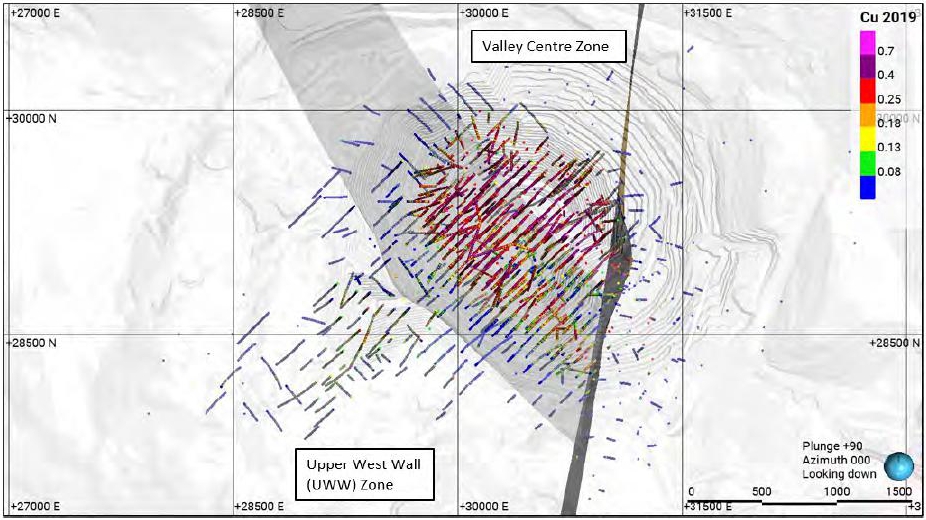
Note: Figure prepared by Teck, 2025. Lornex fault (black plane striking north–south) and the administration boundary between Valley center zone and Upper West Wall zone (medium-grey plane striking northwest–southeast).
Figure 14-1: Plan View, Drilling Showing Copper Assay Results, Valley Deposit
| October 2025 | Page 14- |
|
|
NI 43-101 Technical Report on Highland Valley Copper Operations British Columbia |

Note: Figure prepared by Teck, 2025. Lornex fault (black plane striking north–south) and the administration boundary between Valley center zone and Upper West Wall zone (medium-grey plane striking northwest–southeast.
Figure 14-2: Plan View, Drilling Showing Molybdenum Assay Results, Valley Deposit
| October 2025 | Page 14- |
|
|
NI 43-101 Technical Report on Highland Valley Copper Operations British Columbia |
Merging the core drill hole and blasthole model datasets was considered acceptable because:
| · | Both copper and molybdenum datasets display similar grades and trends in both planar and vertical cross-sections; |
| · | The blasthole data set better defines grade shell boundaries where the blasthole data exists due to greater data density. |
Two copper grade shells, one at ≥0.25% Cu, and the second at ≤0.25% but ≥0.08% Cu, and two molybdenum grade shells at ≥0.007% and ≤0.007% but ≥0.002% Mo, were created (Figure 14-3, Figure 14-4).
Grade shell thresholds were determined by a statistical and visual analysis of the core drill hole raw assays using Snowden Supervisor V9 software. The Valley grade shells were restricted by the Lornex fault to the east and overlying overburden–rock surface.
Visual checks were completed on planar and vertical cross sections defined in Leapfrog. This validation indicated that the grade shells were acceptable, and consistent with the drill hole data.
| 14.2.3 | EXPLORATORY DATA ANALYSIS |
Exploratory data analysis was completed.
The raw core drill hole assay data was first checked using log probability plots to identify apparent inflections of the data, which might indicate changes between statistically discrete stationary populations necessary for estimation. A Valley copper threshold at 0.25% copper was identified in the inflection point observed in the log probability plot. There was no clear break visible in the Valley molybdenum log probability plot.
Decile values were analyzed in Snowden Supervisor to help determine appropriate low-grade thresholds for copper and molybdenum to prevent populating higher grades into the peripheral parts of the deposits where there is poor drill hole coverage and geological knowledge. Most of the drilling is clustered in the central portions of the deposit. A value of 0.08% was selected for copper, 0.007% and 0.002% for molybdenum.
Histograms, log probability plots, and descriptive statistics were used to confirm that the composited sample populations in each estimation domain were approximately stationary (single stationary grade population, showing a single orientation and being geologically homogenous).
Copper and molybdenum grade shells boundaries were analyzed with Leapfrog Edge. Valley mineralized domains were treated as firm to adjacent domains except for the Avalanche domain, which was treated as a hard boundary.
| October 2025 | Page 14- |
|
|
NI 43-101 Technical Report on Highland Valley Copper Operations British Columbia |
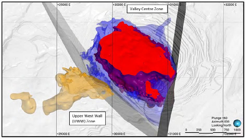
Note: Figure prepared by Teck, 2025. Red represents the ≥0.25% copper grade shell, blue represents the ≥0.08% copper grade shell in Valley center zone, and orange represents the ≥0.08% copper grade shell in Valley Upper West wall zone.
Figure 14-3: Copper Grade Shell, Valley Deposit
| October 2025 | Page 14- |
|
|
NI 43-101 Technical Report on Highland Valley Copper Operations British Columbia |

Note: Figure prepared by Teck, 2025. Red represents the ≥0.007% molybdenum grade shell, orange represents the ≥0.002% molybdenum grade shell in Valley center zone and purple represents the ≥0.007% molybdenum grade shell, light blue represents the ≥0.002% molybdenum grade shell in Valley Upper West wall zone.
Figure 14-4: Molybdenum Grade Shell, Valley Deposit
| October 2025 | Page 14- |
|
|
NI 43-101 Technical Report on Highland Valley Copper Operations British Columbia |
| 14.2.4 | DENSITY ASSIGNMENT |
Bulk density values do not display a lot of variation, and production history and independent ongoing testing have supported the use of single values for lithologies.
The bulk density value for Bethsaida rock type, dominant in the Valley deposit, is 2.63 kg/m3.
The overburden covering part of the Valley deposit consists of several layers with varying bulk density values ranging from 1.85 kg/m3 to 3.13 kg/m3, with a mean of 2.43 kg/m3.
| 14.2.5 | COMPOSITES |
The available assay data consist of a combination of constant 10 ft. (~3.05 m) historical intervals and intervals of variable sample lengths. Historical sample intervals did not consider major breaks in geological parameters; however, during more recent drilling programs (2011 onwards) sample intervals were defined as required by the geologists to honour major breaks in lithological and structural contacts. The minimum sample length is 0.5 m, and the maximum sample length is 2 m for PQ core and 3 m for HQ and NQ core. Most assay sample intervals are either 1 m, 2 m, or 3 m in length for both copper and molybdenum. A 5 m composite length was selected as it was the best compatible length option relative to the 15 m block height.
| 14.2.6 | GRADE CAPPING/OUTLIER RESTRICTIONS |
Capping analysis was completed on drill hole composites using Snowden Supervisor V9.0 software. Histograms and cumulative frequency distributions were analyzed by grade zone domain to identify high-grade outliers and determine an appropriate capping value for each domain as required. Visual review of the distribution and location of outliers indicated whether they could be sub-domained; otherwise, a capped grade was applied. This capping approach was applied for both copper and molybdenum in each domain used in estimation. Most domains were capped. This resulted in a metal reduction range of 0.1–10.7% for copper, and a metal reduction range of 1.3–21.5% for molybdenum in the capped composites.
| 14.2.7 | VARIOGRAPHY |
Experimental variography was undertaken in Snowden Supervisor V9.0 software for copper and molybdenum domains. Experimental variography was not performed on the Avalanche domain, since this domain is no longer in situ and composite samples would yield erratic variograms.
Variograms were modelled using a combined dataset of core drill hole 15 m-capped composites and a smaller sub-set of blasthole assays. The core drill hole dataset was limited in comparison to the quantity of blasthole assays. The blasthole model dataset showed better continuity and spatial relationships for copper and molybdenum. Experimental variograms were run on the combined datasets to determine directions and ranges of continuity. The directions and ranges from this analysis were then imposed on the capped composites drill hole dataset, where the nugget and variance contribution parameters were adjusted.
Lag distances were set to approximately half of the drill hole spacing as a starting point to generate both the variogram continuity maps and the experimental variograms. Multiple lag distances were tested throughout the variography process to help achieve the best possible experimental variogram for a given domain.
| October 2025 | Page 14- |
|
|
NI 43-101 Technical Report on Highland Valley Copper Operations British Columbia |
Experimental variograms for each domain were modelled by fitting two spherical mathematical structures to achieve the “best-fit” model for use in the estimation process. Nugget variance values were determined in reference to downhole experimental variograms calculated with a lag distance set equal to the composite length. Given the generally skewed nature of the univariate data, a normal score transform was applied during the variography process with the back-transformed modelled variograms being used in the grade estimation process.
Search ellipses for grade estimation derived from the modelled variograms were visually inspected in Leapfrog Edge/Geo software on level plans and vertical cross-sections along with composite data prior to use in the estimation process. Kriging neighbourhood analyses helped to define optimum search parameters.
| 14.2.8 | ESTIMATION/INTERPOLATION METHODS |
Ordinary kriging (OK) was selected as the grade interpolation method for estimation of copper and molybdenum grades using Leapfrog Edge. This method was used to estimate blocks that lie within the Bethsaida and copper oxide rock units (west of the Lornex fault).
The Avalanche unit grade domains (east of the Lornex fault) were modelled differently, using inverse distance weighting to the second power (ID2), because the Avalanche material is a talus deposit, and it is no longer in situ.
All mineralized copper and molybdenum domains were estimated using a two-pass estimation strategy. Unestimated blocks were left as blank grades.
Table 14-1 summarizes the final copper and molybdenum estimation domains resulting from the EDA process. The domain locations are shown in Figure 14-5 (copper) and Figure 14-6 (molybdenum).
The selection of the maximum and minimum number of composites to be used in the estimation of a given block was based on the results of a kriging neighbourhood analysis. The number of composites used in the estimation ranged from a minimum of 8–10 samples, and a maximum of 12–25 samples. The maximum number of composites per drill hole ranged from four per drill hole for the first pass to five per drill hole for the second pass. A block discretization of 5 (X) x 5 (Y) x 3 m (Z) was used for all domains.
Grade domain boundaries are set as either hard or firm (0–5 m overlap range). The Avalanche and copper oxide domains were set to a hard boundary.
Outlier restrictions (high yields) were implemented on the second pass only, and only in the low-grade background domains, to prevent high grade blow-outs.
| October 2025 | Page 14- |
|
|
NI 43-101 Technical Report on Highland Valley Copper Operations British Columbia |
Table 14-1: Estimation Domains, Valley Deposit
| Element | Domain | Domain Code |
| Cu | Valley Centre <0.08% Cu | 51 |
| Valley Centre 0.25% to ≥0.08% Cu | 52 | |
| Valley Centre ≥0.25% Cu | 53 | |
| Upper West Wall ≥0.08% Cu | 54 | |
| Upper West Wall <0.08% Cu | 55 | |
| Avalanche | 8 | |
| Mo | Valley Centre <0.002% Mo | 61 |
| Valley Centre 0.007% to ≥0.002% Mo | 62 | |
| Valley Centre ≥0.007% Mo | 63 | |
| Upper West Wall ≥0.007% Mo | 64 | |
| Upper West Wall 0.007% to ≥0.002% Mo | 65 | |
| Upper West Wall <0.002% Mo | 66 | |
| Avalanche | 8 |
| October 2025 | Page 14- |
|
|
NI 43-101 Technical Report on Highland Valley Copper Operations British Columbia |

Note: Figure prepared by Teck, 2025. Red represents the ≥0.25% copper grade shell, blue represents the ≥0.08% copper grade shell in Valley center zone, and orange represents the ≥0.08% copper grade shell in Valley Upper West wall zone.
Figure 14-5: Copper Estimation Domains, Valley Deposit
| October 2025 | Page 14- |
|
|
NI 43-101 Technical Report on Highland Valley Copper Operations British Columbia |

Note: Figure prepared by Teck, 2025. Red represents the ≥0.007% molybdenum grade shell, orange represents the ≥0.002% molybdenum grade shell in Valley center zone and purple represents the ≥0.007% molybdenum grade shell, light blue represents the ≥0.002% molybdenum grade shell in Valley Upper West wall zone
Figure 14-6: Molybdenum Estimation Domains, Valley Deposit
| October 2025 | Page 14- |
|
|
NI 43-101 Technical Report on Highland Valley Copper Operations British Columbia |
Variogram anisotropies were used to define the search ellipses for copper and molybdenum grade model interpolation. Where appropriate, local variable anisotropy copper and molybdenum surfaces were used to define the ellipsoid directions for selected copper and molybdenum center domains. In most cases, the search neighborhood consisted of an anisotropic ellipsoid of approximately 150 x 150 x 100 m for pass one and 300 x 300 x 200 m for pass two.
| 14.2.9 | VALIDATION |
A review of plan and vertical cross-sections showing block values, composite values, domain boundaries, and search ellipse traces indicated no material biases or errors.
Statistical comparisons for copper and molybdenum between ordinary kriged and nearest neighbour models, and capped composite samples did not identify any obvious errors and showed that the estimates reasonably honour the sample data.
Swath plots to compare declustered mean composite grades, kriged grades and nearest neighbour grades (representing declustered grade distribution) were completed for copper and molybdenum.
The swath plots for the copper and molybdenum domains (except the Valley Avalanche domains, which were not included) exhibit a good overall correlation between the models. Deviations between swath trends highlighted areas where the drilling is sparse and/or grade shell artefacts in the models may be present.
A review of available production data against the Mineral Resource model indicated good correlation between Mineral Resource model, grade control model, and mill production. All three key parameters, tonnage, copper grade, and copper metal, are within a ±5% tolerance, providing additional confidence in the Mineral Resource model and estimation methodology.
| 14.2.10 | CLASSIFICATION OF MINERAL RESOURCES |
Drill spacing supporting the Measured Mineral Resource confidence category aimed for ±15% accuracy in quarterly production estimates 90% of the time, albeit modified slightly by also taking into account geological knowledge and mining experience, variography and other statistics, and past reconciliation results.
Similarly, the drill spacing recommendations supporting the Indicated Mineral Resource confidence category aimed for ±15% accuracy in annual production estimates 90% of the time, again modified slightly, as for the Measured Mineral Resource.
The drill spacing recommendations supporting the Inferred Mineral Resource confidence category were based on double the recommended spacings for the Indicated Mineral Resource confidence category.
Valley Mineral Resources are classified based on the parameters in Table 14-2.
| October 2025 | Page 14- |
|
|
NI 43-101 Technical Report on Highland Valley Copper Operations British Columbia |
Table 14-2: Resource Confidence Classifications, Valley Deposit
| Confidence Classification | Area | Criteria |
| Measured | Valley Centre | Three drill holes within an average distance of 70 m |
| Valley Upper West Wall | Three drill holes within an average distance of 45 m | |
| Indicated | Valley Centre | Three drill holes within an average distance of 115 m |
| Valley Upper West Wall | Three drill holes within an average distance of 70 m | |
| Inferred | Valley Centre | Three drill holes within an average distance of 195 m |
| Valley Upper West Wall | Three drill holes within an average distance of 100 m | |
| Avalanche | Talus deposit – not in-situ |
| 14.2.11 | CUT-OFF CRITERIA |
Teck uses a copper-equivalent grade (CuEq) for Mineral Resources reporting.
A molybdenum factor is determined to represent the economic value of a quantity of molybdenum in the mill feed compared to an equal quantity of copper, calculated in the following formula where charges and costs are expressed in dollars per tonne of payable metal:

Copper-equivalent grade models are created using the following formula:
| · | CuEq% = Cu% + (Mo% x molybdenum factor). |
Metal grades within the Valley pit’s Avalanche unit were disregarded, due to uncertainty of their recovery as a consequence of oxidization and clay content.
While applying the cut-off, the calculated CuEq% for each block is downgraded if the block is coded as an “oxide” rock type. “Oxide” rock types have copper oxide (CuOx) percentages >15% of the total copper percentage, and for these particular blocks only the unoxidized copper fraction is included in the CuEq% calculation, i.e., Cu% x (1 – CuOx%) is used instead of Cu%, when CuOx% >15% of the total copper.
For Mineral Resource estimates, a 0.10% CuEq cut-off and a 2.5 molybdenum factor were used.
The molybdenum factor was calculated from the formula above using averages taken from the mine plan, including the metal prices specified in Section 14.6. The cut-off grade was calculated from the total costs and the average grade from the mine plan using the following formula.

where the net revenue is the gross revenue for copper and molybdenum minus treatment, refining, and roasting charges and freight and marketing costs.
All calculations were made using values from 2028–2046, the periods following the planned mill upgrades.
| October 2025 | Page 14- |
|
|
NI 43-101 Technical Report on Highland Valley Copper Operations British Columbia |
| 14.3 | Lornex |
| 14.3.1 | LITHOLOGIES |
Rock types were defined based on the current understanding of geology and mineralization controls. Mineralization occurs east of the Lornex Fault hanging wall contact. Skeena, Bethsaida, and copper oxide (CuOx) codes were used to define domains for the estimation of copper and molybdenum.
| 14.3.2 | MODELLING APPROACH |
The lack of historic drill core has made it difficult to model geological features that control mineralization, such as alteration, lithology, or structure. Grade shells were developed to define domains that represent appropriate controls on mineralization for estimation purposes.
Plan views of the distribution of the drill holes showing copper and molybdenum assays are provided in Figure 14-7 and Figure 14-8 respectively. The copper grade shells are shown in Figure 14-9, and the location of the molybdenum grade shells is provided in Figure 14-10.
Grade shell thresholds were determined by a statistical and visual analysis of the core drill hole raw assays in using Snowden Supervisor V9 software. The Valley grade shells were restricted by the Lornex fault to the east and overlying overburden–rock surfaces.
Visual checks were completed on planar and vertical cross sections defined in Leapfrog Geo. This validation indicated that the grade shells were acceptable, and consistent with the drill hole data.
| 14.3.3 | EXPLORATORY DATA ANALYSIS |
Exploratory data analysis was completed.
The raw core drill hole assay data was first checked using log probability plots to identify apparent inflections of the data, which might indicate changes between statistically discrete stationary populations necessary for estimation. A Lornex copper threshold at 0.30% Cu was identified in the inflection point observed in the log probability plot.
Decile values were analyzed in Snowden Supervisor to help determine appropriate low-grade thresholds for copper and molybdenum to prevent populating higher grades into the peripheral parts of the deposits where there is poor drill hole coverage and geological knowledge. Most of the drilling is clustered in the central portions of the deposit. A value of 0.08% was selected for copper, 0.007% and 0.002% for molybdenum.
Histograms, log probability plots, and descriptive statistics were used to confirm that the composited sample populations in each estimation domain were stationary.
Copper and molybdenum grade shells boundaries were analyzed with Leapfrog Edge. Lornex mineralized domains were treated as firm to adjacent domains except for the hanging wall contact of the Lornex fault, which was treated as a hard boundary.
| October 2025 | Page 14- |
|
|
NI 43-101 Technical Report on Highland Valley Copper Operations British Columbia |
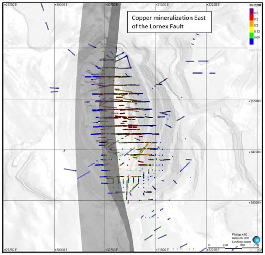
Note: Figure prepared by Teck, 2025. Lornex fault (black plane striking north-south) boundary between the barren Bethsaida rock to the west and the mineralized Skeena to the east. Drill holes are showing copper assays (%).
Figure 14-7: Plan View, Drilling Showing Copper Assay Results, Lornex Deposit
| October 2025 | Page 14- |
|
|
NI 43-101 Technical Report on Highland Valley Copper Operations British Columbia |

Note: Figure prepared by Teck, 2025. Lornex fault (black plane striking north–south) boundary between the barren Bethsaida rock to the west and the mineralized Skeena to the east. Drill holes are show molybdenum assays (%).
Figure 14-8: Plan View, Drilling Showing Molybdenum Assay Results, Lornex Deposit
| October 2025 | Page 14- |
|
|
NI 43-101 Technical Report on Highland Valley Copper Operations British Columbia |
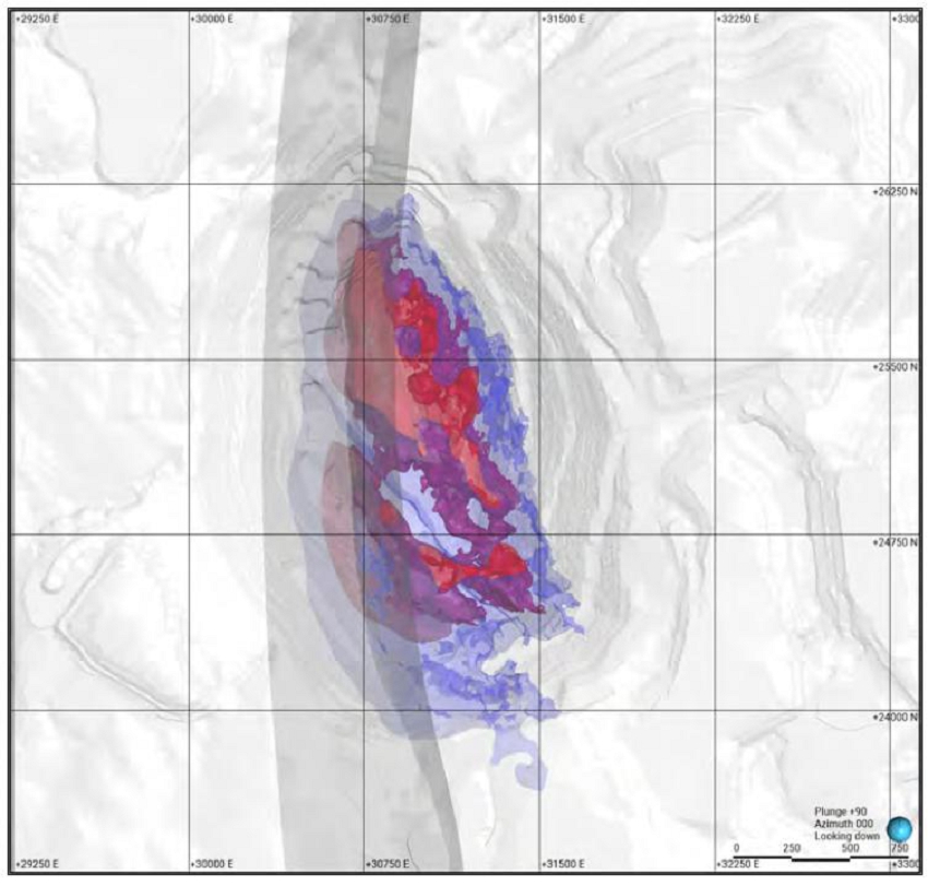
Note: Figure prepared by Teck, 2025. Red represents the ≥0.30% copper grade shell, blue represents the ≤0.08% copper grade shell.
Figure 14-9: Copper Grade Shells, Lornex Deposit
| October 2025 | Page 14- |
|
|
NI 43-101 Technical Report on Highland Valley Copper Operations British Columbia |

Note: Figure prepared by Teck, 2025. Red represents the ≥0.007% molybdenum grade shell and the orange represents the ≥0.002% molybdenum grade shell.
Figure 14-10: Molybdenum Grade Shells, Lornex Deposit
| October 2025 | Page 14- |
|
|
NI 43-101 Technical Report on Highland Valley Copper Operations British Columbia |
| 14.3.4 | DENSITY ASSIGNMENT |
Bulk density values do not display much variation, and production history and independent ongoing testing has supported the use of single values for the lithologies.
The bulk density value for mineralized Skeena rock type located east of the hanging wall of the Lornex fault is 2.60 kg/m3. Non mineralized Bethsaida rock type located west of the Lornex fault was assigned a bulk density of 2.63 kg/m3.
The pit wall deformation zone (Figure 14-11) was assigned a reduced bulk density of 2.50 kg/m3. The deformation zone has shifted from its original position and has moved over 10 m since mining began.
The thin overburden unit covering parts of the Lornex deposit consists of till and was assigned a bulk density of 2.10 kg/m3.
| 14.3.5 | COMPOSITES |
The composite approach was the same as that outlined in Section 14.2.5 for the Valley deposit.
| 14.3.6 | GRADE CAPPING/OUTLIER RESTRICTIONS |
Capping analysis was completed on drill hole composites using Snowden Supervisor V8.13 software. Histograms and cumulative frequency distributions were analyzed by grade zone domain to identify high-grade outliers and determine an appropriate capping value for each domain as required. Visual review of the distribution and location of outliers indicated whether they could be sub-domained; otherwise, a capped grade was applied. This capping approach was applied for both copper and molybdenum in each domain used in estimation. Most domains were capped. This resulted in a metal reduction range of 0.1–4.0% for copper, and a metal reduction range of 0.5–34.7% for molybdenum in the capped composites.
| 14.3.7 | VARIOGRAPHY |
The variography approach was the same as that outlined in Section 14.2.7 for the Valley deposit.
| 14.3.8 | ESTIMATION/INTERPOLATION METHODS |
Ordinary kriging was selected as the grade interpolation method for estimation of copper and molybdenum grades using Leapfrog Edge. This method was used to estimate blocks that lie within the Skeena and copper oxide rock units. The blocks were estimated in a two-pass strategy for each grade domain. Unestimated blocks were left as blank grades.
Table 14-3 summarizes the final copper and molybdenum estimation domains resulting from the exploratory data analysis process. The domains are shown in Figure 14-12 (copper) and Figure 14-13 (molybdenum).
| October 2025 | Page 14- |
|
|
NI 43-101 Technical Report on Highland Valley Copper Operations British Columbia |
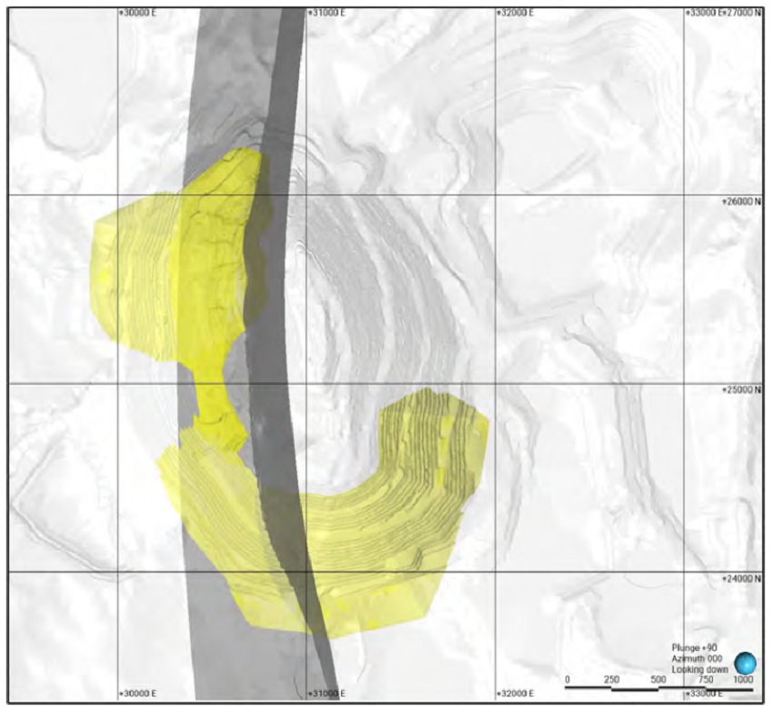
Note: Figure prepared by Teck, 2025. Lornex fault (black plane striking north-south) boundary between the barren Bethsaida rock to the west and the mineralized Skeena to the east. . The yellow solid represents the >10 m deformation zone.
Figure 14-11: Deformation Density Downgrade, Lornex Deposit
| October 2025 | Page 14- |
|
|
NI 43-101 Technical Report on Highland Valley Copper Operations British Columbia |
Table 14-3: Resource Model Estimation Domains, Lornex Deposit
| Element | Domain | Domain Code |
| Cu | North limb ≥ 0.30% Cu | 230N |
| North limb 0.30% to ≥ 0.08% Cu | 208N | |
| North limb < 0.08% Cu | 207N | |
| South limb ≥0.30% Cu | 230S | |
| South limb 0.30% to ≥ 0.08% Cu | 208S | |
| South limb < 0.08% Cu | 207S | |
| Bethsaida salt–pepper | BSP | |
| Unmineralized Bethsaida | 206 | |
| Mo | North Limb ≥ 0.007% Mo | 301 |
| North Limb 0.007% to ≥ 0.002% Mo | 302 | |
| North Limb < 0.002% Mo | 303 | |
| South Limb ≥ 0.007% Mo | 304 | |
| South Limb 0.007% to ≥ 0.002% Mo | 305 | |
| South Limb < 0.002% Mo | 306 | |
| Unmineralized Bethsaida | Bethsaida |
| October 2025 | Page 14- |
|
|
NI 43-101 Technical Report on Highland Valley Copper Operations British Columbia |

Note: Figure prepared by Teck, 2025. Red represents the ≥0.30% copper grade shell, blue represents the ≤0.08% copper grade shell.
Figure 14-12: Copper Estimation Domains, Lornex Deposit
| October 2025 | Page 14- |
|
|
NI 43-101 Technical Report on Highland Valley Copper Operations British Columbia |
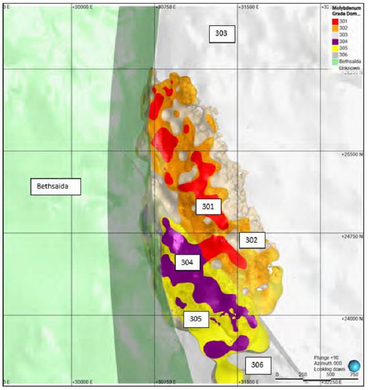
Note: Figure prepared by Teck, 2025. Red represents the ≥0.007% molybdenum grade shell and the orange represents the ≥0.002% molybdenum grade shell.
Figure 14-13: Molybdenum Estimation Domains, Lornex Deposit
Normal score variograms were modeled for copper and molybdenum to account for potential clustering and/or the proportional effect in skewed distributions. The variography modeling was conducted in Snowden Supervisor and back-transformed accordingly. All back-transformed parameters were manually captured into Leapfrog Edge. Grade domain boundaries were set with a firm overlap range of 3–5 m, while the copper oxide domain was always set to a hard boundary.
| October 2025 | Page 14- |
|
|
NI 43-101 Technical Report on Highland Valley Copper Operations British Columbia |
Kriging neighborhood analyses and sensitivity analyses of the search parameters were conducted for the grade domains, revealing that a two-pass strategy yielded the best results. Discretization was set to 5 (X) x 5 (Y) x 3 m (Z). In most cases, the search neighborhood consisted of an anisotropic ellipsoid of approximately 125 x 125 x 70 m for the first pass and 500 x 300 x 200 m for the second pass. The number of composites used in the estimation ranged from a minimum of 9–10 samples to a maximum of 16–25 samples, with a maximum of four composites per drill hole for the first pass and five composites per drill hole for the second pass. Octant search parameters were applied for both passes. Outlier restrictions (high yields) were implemented only on the second pass, and only in the low-grade background domains to prevent high-grade blow-outs.
| 14.3.9 | VALIDATION |
A review of plan and vertical cross-sections showing block values, composite values, domain boundaries, and search ellipse traces indicated no material biases or errors.
Statistical comparisons for copper and molybdenum between ordinary kriged and nearest neighbour models, and capped composite samples did not identify any obvious errors and showed that the estimates reasonably honour the sample data.
Swath plots to compare declustered mean composite grades, kriged grades and nearest neighbour grades (representing declustered grade distribution) were completed for copper and molybdenum. Deviations between swath trends highlighted areas where the drilling is sparse and grade shell artefacts in the models may be present.
A review of available production data against the resource model indicated that good correlation between resource models, grade control models, and mill production. All three key parameters, tonnage, copper grade, and copper metal, are within a ±5% tolerance, providing additional confidence in the resource model and estimation methodology.
| 14.3.10 | CLASSIFICATION OF MINERAL RESOURCES |
Mineral Resources were classified using the same approach as that outlined in Section 14.2.10 for the Valley deposit. The resulting classification criteria are summarized in Table 14-4.
| 14.3.11 | CUT-OFF CRITERIA |
The approach and criteria used were the same as those outlined in Section 14.2.11 for the Valley deposit.
| October 2025 | Page 14- |
|
|
NI 43-101 Technical Report on Highland Valley Copper Operations British Columbia |
Table 14-4: Resource Confidence Classifications, Lornex Deposit
| Confidence Classification | Criteria |
| Measured | Three drill holes within an average distance of 65 m |
| Indicated | Three drill holes within an average distance of 90 m |
| Inferred | Three drill holes within an average distance of 160 m |
| 14.4 | Highmont |
| 14.4.1 | LITHOLOGIES |
The Highmont rock type model contains three rock types, Skeena, CuOx and Bethsaida codes, which were used to define domains for the estimation of copper and molybdenum.
| 14.4.2 | MODELLING APPROACH |
The lack of historic drill core has made it difficult to model geologic features that control mineralization, such as alteration, lithology, or structure. Grade shells were developed to define domains that represent appropriate controls on mineralization for estimation purposes.
Plan views of the distribution of the drill holes showing copper and molybdenum assays are provided in Figure 14-14 and Figure 14-15 respectively.
The Highmont data set used in implicit modelling was a combination of 15 m composite drill hole assays and the blasthole grade dataset (blastholes are drilled 16.5 m depth). Merging the core drill hole and blasthole model datasets was considered acceptable because:
| · | Both copper and molybdenum datasets display similar grades and trends in both planar and vertical cross-sections. |
| · | The blasthole data set better defines grade shell boundaries where the blasthole data exists due to greater data density. |
One copper grade shell at ≥0.08% copper and one molybdenum grade shell at ≥0.005% molybdenum were created (Figure 14-16 and Figure 14-17).
Grade shell thresholds were determined by a statistical and visual analysis of the core drill hole raw assays in using Supervisor V8.15 software. The Highmont grade shells were restricted by the Waterhole fault and an overlying overburden–rock surface.
Visual checks were completed on planar and vertical cross sections defined in Leapfrog Geo. This validation indicated that the grade shells were acceptable, and consistent with the drill hole data.
| October 2025 | Page 14- |
|
|
NI 43-101 Technical Report on Highland Valley Copper Operations British Columbia |

Note: Figure prepared by Teck, 2025. Waterhole fault (black plane striking southwest–northeast), separating Zones 1 and 4 from Zone 5 and administration boundary (vertical red plane striking northwest-southeast) separating Zone 1 (East pit) from Zone 4 (South).
Figure 14-14: Plan View, Drilling Showing Copper Assay Results, Highmont Deposit
| October 2025 | Page 14- |
|
|
NI 43-101 Technical Report on Highland Valley Copper Operations British Columbia |

Note: Figure prepared by Teck, 2025. Waterhole fault (black plane striking southwest–northeast), separating Zones 1 and 4 from Zone 5 and administration boundary (vertical red plane striking northwest-southeast) separating Zone 1 (East pit) from Zone 4 (South).
Figure 14-15: Plan View, Drilling Showing Molybdenum Assay Results, Highmont Deposit
| October 2025 | Page 14- |
|
|
NI 43-101 Technical Report on Highland Valley Copper Operations British Columbia |

Note: Figure prepared by Teck, 2025. Blue, red, and green solids represent ≥0.08% copper grade shells. Waterhole fault (black plane striking southwest-northeast), separating Zones 1 and 4 from Zone 5 and administration boundary (vertical red plane striking northwest-southeast) separating Zone 1 (East pit) from Zone 4 (south).
Figure 14-16: Copper Grade Shell, Highmont Deposit
| October 2025 | Page 14- |
|
|
NI 43-101 Technical Report on Highland Valley Copper Operations British Columbia |

Note: Figure prepared by Teck, 2025. Blue, red, and green solids represent ≥0.005% molybdenum grade shells. Waterhole fault (black plane striking southwest-northeast), separating Zones 1 and 4 from Zone 5 and administration boundary (vertical red plane striking northwest-southeast) separating Zone 1 (East pit) from Zone 4 (South).
Figure 14-17: Molybdenum Grade Shell, Highmont Deposit
| October 2025 | Page 14- |
|
|
NI 43-101 Technical Report on Highland Valley Copper Operations British Columbia |
| 14.4.3 | EXPLORATORY DATA ANALYSIS |
Exploratory data analysis was completed.
The raw core drill hole assay data was first checked using log probability plots to identify apparent inflections of the data, which might indicate changes between statistically discrete stationary populations necessary for estimation. The Highmont log probability plots for copper and molybdenum did not show any clear breaks in the population distribution.
Decile values were analyzed in Supervisor to help determine appropriate low-grade thresholds for copper and molybdenum to prevent populating higher grades into the peripheral parts of the deposits where there is poor drill hole coverage and geological knowledge. Most of the drilling is clustered in the central portions of the deposit. A value of 0.08% was selected for copper and 0.005% for molybdenum.
Histograms, log probability plots, and descriptive statistics were used to confirm that the composited sample populations in each estimation domain were stationary.
Copper and molybdenum grade shells boundaries were analyzed with Leapfrog Edge. Estimation used adjacent domain boundaries as firm boundaries, except for the Waterhole fault, which was treated as a hard boundary.
| 14.4.4 | DENSITY ASSIGNMENT |
Bulk density values do not display much variation, and production history and independent ongoing testing have supported the use of single values for the lithologies. A bulk density value of 2.60 kg/m3 is used for the Skeena porphyry and the copper oxide rock units. The thin overburden unit covering parts of the Highmont deposit consists of sand and silt layers. This unit was assigned a bulk density of 2.10 kg/m3.
| 14.4.5 | COMPOSITES |
The composites approach was the same as that outlined in Section 14.2.5 for the Valley deposit.
| 14.4.6 | GRADE CAPPING/OUTLIER RESTRICTIONS |
Capping analysis was completed on drill hole composites using Snowden Supervisor V8.15 software. Histograms and cumulative frequency distributions were analyzed by grade zone domain to identify high-grade outliers and determine an appropriate capping value for each domain as required. Visual review of the distribution and location of outliers indicated whether they could be sub-domained; otherwise, a capped grade was applied. This capping approach was applied for both copper and molybdenum in each domain used in estimation. All domains were capped. This resulted in a metal reduction range of 0.6–34.8% for copper, and a metal reduction range of 0.9–35.4% for molybdenum in the capped composites.
| 14.4.7 | VARIOGRAPHY |
The variography approach was the same as that outlined in Section 14.2.7 for the Valley deposit.
| October 2025 | Page 14- |
|
|
NI 43-101 Technical Report on Highland Valley Copper Operations British Columbia |
| 14.4.8 | ESTIMATION/INTERPOLATION METHODS |
Ordinary kriging was selected as the grade interpolation method for estimation of copper and molybdenum grades using Leapfrog Edge. This method was used to estimate blocks that lie within the Skeena rock unit. The blocks were estimated in a two-pass sequence for each grade domain. This multiple search strategy approach progressively estimated grade values into the model to ensure well-informed areas of the model were estimated with local information and any grade smearing was minimized. Unestimated blocks were left as blank grades.
Table 14-5 summarizes the final copper and molybdenum estimation domains resulting from the exploratory data analysis process. The estimation domains are provided in Figure 14-18 (copper) and Figure 14-19 (molybdenum).
Grade domain boundaries are set as to firm (5 m overlap range). The number of composites used in the estimation ranged from a minimum of 9–10 samples, and a maximum of 16–25 samples. Maximum number of composites per drill hole ranged from four per drill hole for the first pass to five per drill hole for the second pass. Octant Search thresholds were applied for both passes. A block discretization of 5 (X) x 5 (Y) x 3 m (Z) was used for all domains.
For most cases, the search neighborhood consists of an anisotropic ellipsoid of approximately 130 x 110 x 80 m for pass one and 400 x 300 x 250 m for pass two. Outlier restrictions (high yields) were implemented on the second pass only, and only in the low-grade background domains, to prevent high grade blow-outs.
| 14.4.9 | VALIDATION |
A review of plan and vertical cross-sections showing block values, composite values, domain boundaries, and search ellipse traces indicated no material biases or errors.
Statistical comparisons for copper and molybdenum between ordinary kriged and nearest neighbour models, and capped composite samples did not identify any obvious errors and showed that the estimates reasonably honour the sample data.
Swath plots to compare declustered mean composite grades, kriged grades and nearest neighbour grades (representing declustered grade distribution) were completed for copper and molybdenum. The swath plots for the copper and molybdenum domains exhibit a good overall correlation between the models. Deviations between swath trends highlighted areas where the drilling is sparse and grade shell artefacts in the models may be present.
There has been no mining at Highmont since 2017. Reconciliation data prior to 2017 indicated an adequate correlation between the resource model with respect to both grade control model and mill production.
| 14.4.10 | CLASSIFICATION OF MINERAL RESOURCES |
Mineral Resources are classified using the same approach and criteria as those outlined in Section 14.2.10 for the Valley deposit. The final classifications are provided in Table 14-6.
| October 2025 | Page 14- |
|
|
NI 43-101 Technical Report on Highland Valley Copper Operations British Columbia |
Table 14-5: Resource Model Estimation Domains, Highmont Deposit
| Element | Domain | Domain Code |
| Cu | Zone 1 <0.08% Cu | 151 |
| Zone 1 ≥ 0.08% Cu | 152 | |
| Zone 2 - Peripheral Structurally controlled | 251 | |
| Zone 3 - Peripheral Structurally controlled | 252 | |
| Zone 3 - Bethsaida | 351 | |
| Zone 4 <0.08% Cu | 451 | |
| Zone 4 ≥ 0.08% Cu | 452 | |
| Zone 5 <0.08% Cu | 551 | |
| Zone 5 ≥ 0.08% Cu | 552 | |
| Composite Dyke | 651 | |
| Breccia | 652 | |
| Mo | Zone 1 <0.005% Mo | 161 |
| Zone 1 ≥ 0.005% Mo | 162 | |
| Zone 2 - Peripheral Structurally controlled | 261 | |
| Zone 3 - Peripheral Structurally controlled | 262 | |
| Zone 3 - Bethsaida | 361 | |
| Zone 4 <0.005% Mo | 461 | |
| Zone 4 ≥ 0.005% Mo | 462 | |
| Zone 5 <0.005% Mo | 561 | |
| Zone 5 ≥ 0.005% Mo | 562 |
| October 2025 | Page 14- |
|
|
NI 43-101 Technical Report on Highland Valley Copper Operations British Columbia |

Note: Figure prepared by Teck, 2025. Blue, red, and green solids represent ≥0.08% copper grade shells. Waterhole fault (black plane striking southwest–northeast), separating Zones 1 and 4 from Zone 5 and administration boundary (vertical red plane striking northwest-southeast) separating Zone 1 (East pit) from Zone 4 (south).
Figure 14-18: Copper Estimation Domains, Highmont Deposit
| October 2025 | Page 14- |
|
|
NI 43-101 Technical Report on Highland Valley Copper Operations British Columbia |

Note: Figure prepared by Teck, 2025. Blue, red, and green solids represent ≥0.005% molybdenum grade shells. Waterhole fault (black plane striking southwest–northeast), separating Zones 1 and 4 from Zone 5 and administration boundary (vertical red plane striking northwest-southeast) separating Zone 1 (East pit) from Zone 4 (south).
Figure 14-19: Molybdenum Estimation Domains, Highmont Deposit
Table 14-6: Resource Confidence Classifications, Highmont Deposit
| Confidence Classification | Criteria |
| Measured | Three drill holes within an average distance of 40 m |
| Indicated | Three drill holes within an average distance of 70 m |
| Inferred | Three drill holes within an average distance of 115 m |
| October 2025 | Page 14- |
|
|
NI 43-101 Technical Report on Highland Valley Copper Operations British Columbia |
| 14.4.11 | CUT-OFF CRITERIA |
The approach was the same as that outlined in Section 14.2.11 for the Valley deposit.
| 14.5 | Bethlehem |
| 14.5.1 | LITHOLOGIES |
The metal distributions by lithology for copper and molybdenum are shown in various figures, with common rock types either separated or grouped. Mean grade versus standard deviation plots and quantile–quantile plots are used to assess potential estimation domains and stationarity, respectively.
Breccias are of particular interest for defining a positive estimation domain due to their high mean grade and low coefficient of variation. However, breccias do not have a primary control on mineralization, which is more related to structure. Mineralized veins from the main copper event cut through both breccias and other rock types, making it challenging to separate metal distribution in adjacent rock types for estimation purposes.
| 14.5.2 | MODELLING APPROACH |
Interpreted 2-D level plan and vertical cross sections form the basis for 3-D modelling of lithological solids. Specifically, 37 vertical sections spaced 30–60 m apart through the deposit combined with four level plans from 1100–1400 m in elevation were used. Digitized sections imported into Leapfrog provided a basis for:
| · | Generating downhole interval model codes used for implicit modelling |
| · | Editing solids with polylines |
| · | Guiding global and/or structural trends on individual lithologies, where necessary. The static section interpretations are honored as closely as possible. |
Individual lithologies were modeled as intrusions or dykes in Leapfrog using the Radial Basis Function algorithm for interpolation. Lithologies that crossed fault blocks and multiple occurrences of the same lithology were modeled separately. The implicit algorithm's model codes provided the primary control for solid generation. Polylines and structural trends did not override the primary data, meaning the downhole interval data in the model codes were always honored. Instead, polylines and trends were used to refine the solids based on interpreted sections and the consideration of all primary data in 3D.
Intrusions were modeled using spheroidal interpolants with a typical range of 100 m, adjusted based on data distribution, density, and lithology complexity. Various Leapfrog parameters were considered to best honor 2-D interpretations unless modified by 3-D data. Younger lithologies were ignored during solid creation, and crosscutting relationships were accounted for by defining the Leapfrog Surface Chronology, with older solids clipped by younger ones.
Implicit modeling in Leapfrog categorized model code segments into primary, ignored, and exterior units. Geology solids were simplified by setting composite filtering thresholds, with practical limits for Bethlehem lithologies. Small, isolated holes and discrete fragments were filtered based on their size and context. Filtering of exterior segments was generally inconsequential, as they mostly consisted of younger late mineral dykes and stocks, which were ignored during rendering.
| October 2025 | Page 14- |
|
|
NI 43-101 Technical Report on Highland Valley Copper Operations British Columbia |
Dykes were modeled as veins or vein systems in Leapfrog. Vein systems grouped individual veins, with vein priority determining how branches were truncated. Veins can also be through going without termination at intersections. This system was effective for modeling sheeted dykes or branch structures, avoiding foreign material in the final volume.
Veins were edited in several ways:
| · | Hanging wall and foot wall points from downhole data can be manually overridden or excluded; |
| · | A best-fit planar or curved reference surface can be fully edited based on known attitudes; |
| · | The vein boundary can be modified to adjust the overall extent; |
| · | Pinch-outs determined by outside lithologies can be excluded manually or entirely; |
| · | Hanging wall and foot wall surfaces can be edited with polylines, but these edits do not override model lithology codes. |
Detailed analysis of lithology and alteration solids did not reveal consistent patterns for defining stationary domains for Mineral Resource estimation. To address this, mineralized grade thresholds were developed based on changes in trend and continuity, identified through cumulative distribution plots. For copper, the global distribution was nearly univariate stationary up to the 99th percentile, with a small change in slope around the 0.2% threshold.
Spatial stationarity was assessed by generating decile grade shell interpolants and evaluating the results on vertical sections and level plans. The most significant shift in continuity occurs between 0.11% and 0.2% copper. Assays within late mineral dykes and stocks were excluded to better model mineralization at the time of emplacement. Based on this analysis, copper mineralized domains were modeled for ≥0.11% but <0.24% Cu and ≥0.24% Cu.
Plan views of the distribution of the drill holes showing copper and molybdenum assays are provided in Figure 14-20 and Figure 14-21, respectively.
Similar analysis for molybdenum resulted in mineralized domains for 0.001%–0.00227% Mo (Jersey), 0.001%–0.004% Mo (Iona), ≥0.00227% Mo (Jersey), and ≥0.004% Mo (Iona).
A leachable copper surface was generated using acid-soluble copper analyses, with thresholds determined in collaboration with the metallurgical group. The mixed sulphide-oxide zone was defined where the proportion of leachable copper was ≥0.15% of the total copper assay. This surface approximated the base of oxidation and aligned with visual observations of copper oxide minerals in drill core. Although copper oxide minerals also occur in moderate- to steeply-dipping through-going structures, these are too localized to be accurately modeled at a block scale. For Mineral Resource estimation purposes, the oxidation surface was used as a boundary for modeling the mixed sulphide–oxide zone.
| October 2025 | Page 14- |
|
|
NI 43-101 Technical Report on Highland Valley Copper Operations British Columbia |
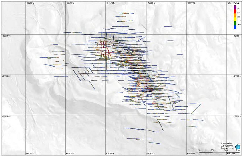
Note: Figure prepared by Teck, 2025. Copper diamond drill hole copper assays
Figure 14-20: Plan View, Drilling Showing Copper Assay Results, Bethlehem Deposit
| October 2025 | Page 14- |
|
|
NI 43-101 Technical Report on Highland Valley Copper Operations British Columbia |

Note: Figure prepared by Teck, 2025.
Figure 14-21 Plan View, Drilling Showing Molybdenum Assay Results, Bethlehem Deposit
| October 2025 | Page 14- |
|
|
NI 43-101 Technical Report on Highland Valley Copper Operations British Columbia |
| 14.5.3 | EXPLORATORY DATA ANALYSIS |
Exploratory data analysis was conducted on primary data (assays) and secondary data (interpreted wireframes) to assess the controls on mineralization. Specifically, the relationship of lithology, alteration, and structure with respect to grade was investigated to assess potential estimation domains. Data sources were interrogated spatially with respect to mineralization, both in 2D on level plans and vertical cross sections, as well as dynamically in 3D. Statistical analysis was undertaken to infer the overall tenor of mineralization, as well as the degree of stationarity associated with different domains.
Table 14-7 summarizes the final copper and molybdenum estimation domains resulting from the exploratory data analysis process. The estimation domains are shown in Figure 14-22 (copper) and Figure 14-23 (molybdenum).
| 14.5.4 | DENSITY ASSIGNMENT |
In 2013 and 2014, a total of 5,383 SG measurements were obtained from drilling activities. The SG data for Bethlehem indicate a narrow range of values, suggesting low density variability throughout the deposit. Despite this, SG values were categorized according to key rock types. These domains were interpolated within hard boundaries using inverse distance weighting to the second power. During the interpolation process, a minimum of seven and a maximum of 14 samples were used, with a limit of three samples per drill hole to ensure at least three drill holes contributed to each block's interpolation. A 500 m isotropic search ellipse was employed. High outliers were top-cut at SG = 3 and low outliers were bottom-cut at SG = 2, with outliers being randomly distributed, yielding a mean SG of 2.67.
| 14.5.5 | COMPOSITES |
The assay data includes constant 10-foot intervals from legacy datasets and variable-length samples from recent drilling, with lengths ranging from 0.5–3 m. A composite length of 6 m was chosen to minimize splitting of sample intervals and to be compatible with the resource model's block height.
Composites were calculated in GEMS™ from the bottom of the drill hole up, respecting geological domain boundaries. The total composite length was 144,003 m, with a residual length of 5,973 m, and there was no grade bias associated with shorter composite lengths. All composites were included in the 2016 resource model estimate.
Early-stage metallurgical sampling created 31 missing assays, which were addressed by comparing the length-weighted average copper grade of samples bracketing these gaps. Missing molybdenum assays were more common in un-mineralized parts of the deposit, and a detection limit value was used for missing assays prior to compositing. Drill holes with no molybdenum assays from certain drill campaigns were ignored during the compositing process.
| October 2025 | Page 14- |
|
|
NI 43-101 Technical Report on Highland Valley Copper Operations British Columbia |
Table 14-7: Resource Model Estimation Domains, Bethlehem Deposit
| Element | Domain | Domain Code |
| Cu | Late Spud Stock | 503 |
| Late Forgotten Zone Stock | 504 | |
| Late Dykes | 505 | |
| Late Iona Stock | 506 | |
| Late Jersey Stock | 507 | |
| Jersey Background < 0.11% Cu | 508 | |
| Iona Background < 0.11% Cu | 5082 | |
| Huestis Background < 0.11% Cu | 5083 | |
| Jersey ≥ 0.11% Cu < 0.24% Cu | 511 | |
| Iona ≥ 0.11% Cu < 0.24% Cu | 5112 | |
| Huestis ≥ 0.11% Cu < 0.24% Cu | 5113 | |
| Jersey ≥ 0.24% Cu | 524 | |
| Iona ≥ 0.24% Cu | 5242 | |
| Mo | Late Spud Stock | 703 |
| Late Forgotten Zone Stock | 704 | |
| Late Dykes | 705 | |
| Late Iona Stock | 706 | |
| Late Jersey Stock | 707 | |
| Jersey Background | 708 | |
| Iona Background | 7082 | |
| Huestis Background | 7083 | |
| Jersey ≥ 0.001% Mo <0.00227% Mo | 710 | |
| Iona ≥ 0.001% Mo <0.004% Mo | 7102 | |
| Huestis ≥ 0.001% Mo | 7103 | |
| Jersey ≥ 0.00227% Mo | 722 | |
| Iona ≥ 0.004% Mo | 740 |
| October 2025 | Page 14- |
|
|
NI 43-101 Technical Report on Highland Valley Copper Operations British Columbia |

Note: Figure prepared by Teck, 2025. Blue represents ≥0.08% copper grade shell
Figure 14-22: Copper Estimation Domains, Bethlehem Deposit
| October 2025 | Page 14- |
|
|
NI 43-101 Technical Report on Highland Valley Copper Operations British Columbia |
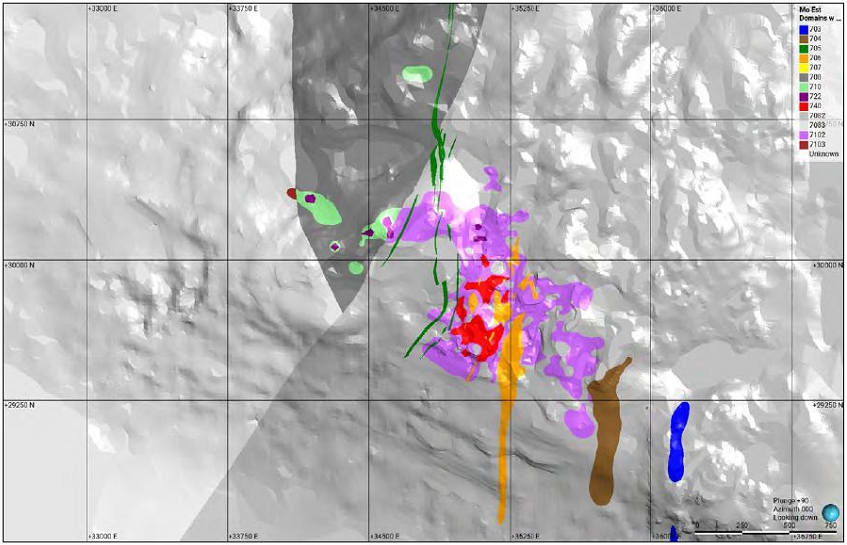
Note: Figure prepared by Teck, 2025. Yellow represents ≥0.005% molybdenum grade shell
Figure 14-23: Molybdenum Estimation Domains, Bethlehem Deposit
| October 2025 | Page 14- |
|
|
NI 43-101 Technical Report on Highland Valley Copper Operations British Columbia |
| 14.5.6 | GRADE CAPPING/OUTLIER RESTRICTIONS |
An analysis of the composite grades was conducted using Snowden Supervisor, version 8.2, software. Histograms and cumulative frequency distributions were used to determine the appropriate top-cut values for copper and molybdenum in each domain. A spatial review of the composites selected for top-cutting confirmed that their locations are disparate, eliminating the possibility of sub-domaining high-grade composite clusters.
For molybdenum, domains 704, 708, and 7103 show higher metal reductions due to their low absolute mean grades, making them particularly sensitive to outliers. However, these domains are outside the current mine plan. Additionally, because the absolute molybdenum values are very low, the impact of molybdenum top-cuts on the final CuEq grades is negligible.
| 14.5.7 | VARIOGRAPHY |
A spatial continuity analysis (variography) was conducted on the top-cut 6 m composites using Snowden Supervisor software to generate and model experimental variograms for all copper and molybdenum domains. This analysis involved three stages:
| · | Determining principal axis directions by examining variogram continuity maps; |
| · | Calculating and optimizing the experimental variograms in these principal directions; |
| · | Modeling the experimental variograms by fitting mathematical model structures. |
Principal axis directions were selected based on both the calculated variogram continuity maps and known mineralized vein attitudes. As veins are planar features, their consistency with the dip plane continuity maps in Supervisor was validated before choosing the principal directions. Experimental variograms for each 10° segment (ray) of the variogram continuity maps (18 rays per map) were reviewed along with the contoured continuity maps to select the directions of maximum continuity.
Lag distances approximating half the drill hole spacing were initially used to generate variogram continuity maps and experimental variograms. Due to irregular drill hole spacing at Bethlehem, multiple lag distances were tested to achieve the best possible experimental variogram for each domain. Most domains produced reasonable experimental variograms with angular tolerance thresholds of 10° in- and off-plane, though tolerances up to 25° were used when insufficient sample pairs were found.
Experimental variograms for each domain were modeled by fitting three spherical mathematical structures to achieve the best-fit model for estimation. Nugget variance values were determined from downhole experimental variograms with a lag distance equal to the 6 m composite length. Normal score transforms applied during variography were back-transformed, and these back-transformed modeled variograms were used in the grade estimation process. Search ellipses for grade estimation, derived from the modeled variograms, were visually inspected in GEMS on level plans and vertical cross-sections along with composite data before use in the estimation process.
| October 2025 | Page 14- |
|
|
NI 43-101 Technical Report on Highland Valley Copper Operations British Columbia |
| 14.5.8 | ESTIMATION/INTERPOLATION METHODS |
Ordinary kriging was chosen as the grade interpolation method for estimating copper and molybdenum grades, except for domains 503 and 703 (Late Spud Stock), which were assigned mean composite grades due to limited data. The Late Spud Stock is a barren unit near Spud Lake, treated with a hard boundary to prevent grade-smearing.
A minimum of seven and a maximum of 14 composites were used in each estimation pass, based on a change of support analysis. A restriction of a maximum of three composites per drill hole was applied to ensure composites from at least three drill holes informed block estimates, implicitly declustering the samples. A block discretization of 10 (X) x 10 (Y) x 3 m (Z) was used for all domains, and negative kriging weights were permitted.
A percent model approach was chosen for the Bethlehem model update to accurately represent barren late mineral dykes and stocks. This method calculates and stores the proportion of each block corresponding to individual domains, ensuring appropriate representation of all domains regardless of geometry. The drawback is the inability to know the exact spatial location within a block without referencing the original 3D domain solids.
Estimation domains for copper and molybdenum were organized in block model folders with attributes for multiple grade iterations, domain code, percent of domain solid, density, and nearest neighbor grade. Additional statistical attributes included the number of points used, distance to the closest composite, slope of regression, block variance, kriging variance, minimum kriging weight, mean distance for composites, and estimation pass.
A ‘Combined’ block model folder was used for final block estimates, with grades weighted according to the percent model. Scripts were used to calculate final block grades and ensure estimates summed to 100%. The ‘Combined’ folder also contained attributes for copper equivalent, density, classification and risk, leachable copper, copper and molybdenum recovery, in-pit dump "ore," and block classification for mine planning purposes.
The search strategy for estimating copper grades used a five-pass approach, with each pass estimating grades only in previously un-estimated blocks. Search distances for each pass were based on changes in slope along experimental variogram profiles. The first pass treated adjacent domain boundaries as soft, the second as firm, and the third and fourth as hard. A fifth pass was added to estimate peripheral blocks using fewer samples. Late dyke and stock domain estimation used a similar three-pass strategy with hard boundaries for the first two passes.
For molybdenum grade estimation, a three-pass approach was used, with search distances based on variogram profiles. To prevent over-estimation from high-grade copper outliers, high-grade search restrictions were applied. These restrictions excluded high-grade composites beyond a certain distance during the estimation process.
| October 2025 | Page 14- |
|
|
NI 43-101 Technical Report on Highland Valley Copper Operations British Columbia |
| 14.5.9 | VALIDATION |
Block estimates of copper and molybdenum were validated using several methods, including visual validation; comparison of ordinary kriging and nearest neighbor statistics; swath plots; and change of support.
Visual validation indicated that there are no obvious inconsistencies between block and composite values. Grade smearing/smoothing across domain boundaries has been appropriately managed with estimation pass boundary conditions. Some over-extrapolation of copper grades occurs in the peripheral parts of the deposit, associated with background domains. This is primarily due to a limited number of holes ending with high-grade samples, which is mitigated using high-grade transition values. Block model trends align with the geology and expected anisotropy.
Comparison of the grade-tonnage curves from the ordinary kriged model against the theoretical discrete Gaussian model for Bethlehem suggests the estimation parameters used (including the maximum number of composites) were reasonable and that the degree of smoothing in the ordinary kriged model is within acceptable limits.
| 14.5.10 | CLASSIFICATION OF MINERAL RESOURCES |
Mineral Resources were classified using the same approach as that outlined in Section 14.2.10 for the Valley deposit. The resulting classifications are summarized in Table 14-8.
| 14.5.11 | CUT-OFF CRITERIA |
The approach was the same as that outlined in Section 14.2.12 for the Valley deposit.
| 14.6 | Reasonable Prospects of Eventual Economic Extraction |
The resource pits were based on a Lerchs–Grossmann optimization process using Whittle software with inputs from the mine plan and a set of commodity prices established annually by Teck for Mineral Resource and Mineral Reserve estimation (Table 14-9).
Copper equivalent models, downgraded for the presence of copper oxides by the same calculations presented in Section 14.2.11, were used, as well as the expected recovery and economic assumptions on commodity pricing, site costs, and realization costs.
Potentially mineable blocks were constrained to claims owned by Teck, limiting the southeastern extent of the Highmont Mineral Resource estimate.
Pit shells generated for a revenue factor of 1.0 were used for all areas.
All mining costs were modeled for autonomous Caterpillar 793 trucks being loaded by P&H 4100 shovels. The costs included sustaining capital but not development capital expenditures, assigned as a dollar per tonne to each block.
| October 2025 | Page 14- |
|
|
NI 43-101 Technical Report on Highland Valley Copper Operations British Columbia |
Table 14-8: Resource Confidence Classifications, Bethlehem Deposit
| Confidence Classification | Criteria |
| Measured | Three drill holes within an average distance of 40 m |
| Indicated | Three drill holes within an average distance of 70 m |
| Inferred | Three drill holes within an average distance of 115 m |
Table 14-9: Pit Shell Input Parameters
| Parameter | Units | Lornex | Valley | Highmont | Bethlehem |
| Copper price | US$/lb | 3.80 | |||
| Molybdenum price | US$/lb | 15.20 | |||
| Exchange rate | CAD:USD | 1.31 | |||
| Copper selling cost | US$/recovered lb | 0.239 | |||
| Administration | $/t milled | 2.55 | |||
| Mining | $/t mined | 3.56 | 3.83 | 3.62 | 3.36 |
| Mill and tailings | $/t milled | 5.91 | 6.92 | 6.47 | 9.68 |
| Copper recovery | % | 86.6 | 92.1 | 83.8 | 80.1 |
The milling and tailings-related costs and recoveries in Table 14-9 were established by using post-upgrade averages. Based on the economic model, approximately 15% of the cost was assigned equally to all blocks. The remaining 85% was distributed unequally, based on the average hardness of the mineralization in each of the pits.
Based on geotechnical analysis of the Mineral Reserve pits, pit slopes were input to Whittle to determine dependencies regarding which blocks must be mined in the elevations above a subject block. A geotechnical block model was created for each pit using the slope recommendations provided by the geotechnical consultant. Numerical codes were assigned to each block based on material type, proximity to faulting, and/or area of the mine. All slopes input to Whittle were input as inter-ramp angles, flattened to account for the step-outs dictated by the geotechnical recommendations.
| 14.7 | Mineral Resources Statement |
Mineral Resources are reported in situ, using the 2014 CIM Definition Standards. The Mineral Resources estimate has an effective date of 1 July, 2025 (Table 14-10).
The Qualified Person for the Mineral Resources estimate is Mr. Alex Stewart, P.Geo., a Highland Valley Copper Partnership employee.
| October 2025 | Page 14- |
|
|
NI 43-101 Technical Report on Highland Valley Copper Operations British Columbia |
Table 14-10: Mineral Resource Summary Table
| Deposit/Area | Confidence Category | Tonnage (kt) |
Grade | Contained Metal | ||
| Copper (%) |
Molybdenum (%) |
Copper (kt) |
Molybdenum (kt) |
|||
| Lornex | Measured | 185,020 | 0.256 | 0.0122 | 474 | 23 |
| Indicated | 177,397 | 0.249 | 0.0108 | 442 | 19 | |
| Valley | Measured | 107,377 | 0.297 | 0.0072 | 319 | 8 |
| Indicated | 356,071 | 0.259 | 0.0075 | 924 | 27 | |
| Highmont | Measured | 3,778 | 0.146 | 0.0196 | 6 | 1 |
| Indicated | 15,697 | 0.153 | 0.0203 | 24 | 3 | |
| Bethlehem | Measured | 7,302 | 0.314 | 0.0042 | 23 | 0 |
| Indicated | 4,536 | 0.237 | 0.0038 | 11 | 0 | |
| Total Measured and Indicated | 857,177 | 0.259 | 0.0094 | 2,221 | 80 | |
| Lornex | Inferred | 79,123 | 0.200 | 0.0107 | 158 | 8 |
| Valley | Inferred | 201,892 | 0.200 | 0.0087 | 403 | 18 |
| Highmont | Inferred | 7,004 | 0.187 | 0.0171 | 13 | 1 |
| Bethlehem | Inferred | 3,510 | 0.258 | 0.0025 | 9 | 0 |
| Total Inferred | 291,530 | 0.200 | 0.0094 | 584 | 27 | |
Notes to Accompany Mineral Resource Table:
| 1. | Mineral Resources are reported in situ, using the 2014 CIM Definition Standards, and have an effective date of 1 July, 2025. The Qualified Person for the Mineral Resource estimate is Mr. Alex Stewart, a Highland Valley Copper Partnership employee. |
| 2. | Mineral Resources are reported exclusive of those Mineral Resources converted to Mineral Reserves. Mineral Resources that are not Mineral Reserves do not have demonstrated economic viability. |
| 3. | Mineral Resources are constrained within pit shells. Input parameters included: copper price of US$3.80/lb Cu, molybdenum price of US$15.20/lb Mo; exchange rate of C$:US$ of 1.31; copper selling cost of US$0.239/lb recovered Cu; mining costs that vary be deposit, with averages ranging from $3.36–3.83/t mined; administration costs of $2.55/t milled; mill and tailings costs that range from $5.91–9.68/t milled; variable mill recoveries that range from 80.1–92.1% for copper, and variable pit slope angles by deposit and pit, ranging from 7–51°. Mineral Resources are reported at a copper equivalent cut-off grade of 0.10%. The copper equivalency equation is CuEq% = Cu% + (Mo% x molybdenum factor). The molybdenum factor is determined to represent the economic value of a quantity of molybdenum in the mill feed compared to an equal quantity of copper, and is based on a formula. |
| 4. | Numbers have been rounded and may not sum. |
| October 2025 | Page 14- |
|
|
NI 43-101 Technical Report on Highland Valley Copper Operations British Columbia |
| 14.8 | Factors That May Affect the Mineral Resources Estimate |
Factors that may affect the Mineral Resources estimate include:
| · | Metal price and exchange rate assumptions; |
| · | Changes to the assumptions used to generate the copper equivalent grade cut-off grade; |
| · | Changes in local interpretations of mineralization geometry and continuity of mineralized zones; |
| · | Changes to geological and mineralization shapes, and geological and grade continuity assumptions; |
| · | Density and domain assignments; |
| · | Changes to geotechnical assumptions including pit slope angles; |
| · | Changes to mining and metallurgical recovery assumptions; |
| · | Changes to the input and design parameter assumptions that pertain to the conceptual pit constraining the estimates potentially amenable to open pit mining methods; |
| · | Assumptions as to the continued ability to access the site, retain mineral and surface rights titles, maintain environment and other regulatory permits, and maintain the social license to operate. |
| 14.9 | QP Comment on Item 14 “Mineral Resource Estimates” |
There are no other environmental, legal, title, taxation, socioeconomic, marketing, political or other relevant factors known to the QP that would materially affect the estimation of Mineral Resources that are not discussed in this Report.
| October 2025 | Page 14- |
|
|
NI 43-101 Technical Report on Highland Valley Copper Operations British Columbia |
15 MINERAL RESERVE ESTIMATES
| 15.1 | Introduction |
The design reserve pits were based on a Lerchs-Grossmann optimization process using Whittle software and detailed phased pit designs. Twenty mine phases (nine Valley phases, one Lornex, four Highmont, and six Bethlehem) were devised to prioritize the higher-grade zones within the mineral extraction plan, while maintaining suitable working widths that would enable high productivity mining sequences using large-scale mining equipment.
Mining assumes conventional open pit operations using truck-and-shovel technology. The size of the open pits and the production rates are controlled by site-specific constraints.
| 15.2 | Pit Optimization |
The basis for reserve pit designs is output from Whittle, as described in Section 14.6, but with key differences in the inputs. Although each pit design has evolved in response to changing economics, geotechnical conditions, and geological modeling, the extents were generally determined based on the Whittle inputs at the time that its permitting was initiated. For all pits, this includes lower metal price assumptions from previous corporate metal price guidance than was specified in Table 14-9 for the Mineral Resource constraining pit shells.
Additionally, the Whittle inputs that provided the design basis included Inferred Mineral Resources and a reduction in selling costs to represent the by-product silver and gold byproduct credits received for the copper concentrate, based on historical observations.
Although the pit designs used these parameters, all of the Mineral Reserve estimates within this Report have been estimated with Inferred Mineral Resources converted to waste and no revenues were assumed to be provided by silver and gold.
| 15.3 | Optimization Inputs |
Each pit optimization was completed separately in Whittle using a process similar to that described in Section 14.6, using the most appropriate inputs at the time of the exercise. The Lornex and Bethlehem pit optimizations were performed prior to applications for permitting in 2010 and 2016, respectively. The Valley pit is based on a 2023 optimization and the Highmont pit is based on a 2024 optimization.
In addition to the limitation imposed on the Highmont pit by constraining its extent to Teck’s mineral tenure claims, the Mineral Reserve pit was also constrained to preclude mining through Highmont Creek and the wetlands around it, to the west of the pit.
The Valley pit was restricted at the Whittle phase to exclude mining within 100 m of the nearest paved shoulder of Highway 97, leaving a corridor for service roads and infrastructure.
The Whittle optimization produces pit shells that identify which resource model blocks can be economically mined at a range of metal prices. Detailed work is then required to translate this into executable designs. This stage involves the creation of toes and crests for each bench while smoothing the blocky nature of the Whittle shells. It also includes the addition of haulage ramps, guided by an understanding of the resource models and how the extents of the Whittle shells react to higher and lower metal prices. Additionally, minimum mining widths are introduced to the design, both in the distance from the existing pit walls and in the bottoms of the reserve pits.
| October 2025 | Page 15- |
|
|
NI 43-101 Technical Report on Highland Valley Copper Operations British Columbia |
The minimum width permitted in the designs varies by circumstance, including the length along the bench that will be at that width, consideration for traffic other than the equipment mining the narrow section (access to ramps or other dig faces), and the number of benches below that will experience the same constriction. Typically, a width as low as 45 m was allowed where necessary and any bench less than 70 m was scheduled with reduced productivity. Narrower widths were permitted for the highest benches on some pit walls, which will necessitate either the use of smaller equipment (e.g., dozers) or rehandling to establish extra width for the operational truck and shovel fleet.
The resulting pit designs extend outside of the constraining Mineral Resource pit shells described in Section 14 and shown in the figures in Section 10 in multiple locations, particularly in the Highmont and Bethlehem pits, where the horizontal distance between the shells and the existing pit walls is insufficient for the mining equipment. For the mine plan and Mineral Reserves statement, all material outside of the Mineral Resource shells was converted to waste, regardless of confidence category.
| 15.4 | Cut-off Criteria |
The cut-off grades used for the Mineral Reserves statement vary by pit and by period in the mine plan, and were based on a strategy to maximize the mine plan net present value. Although expressed as a copper-equivalent grade (as described in Section 14.2.11), each pit was assigned a different cut-off to reflect differences in metal recoveries, milling costs, and haulage costs.
Cut-off grades for the Lornex deposit will vary from 0.12–0.16% CuEq over the life of the pit. Cut-off grades used in the Valley pit will range from 0.10–0.16% CuEq; in the Highmont pit from 0.11–0.15% CuEq, and in the Bethlehem pit from 0.16–0.17% CuEq.
| 15.5 | Ore Loss and Dilution |
Ore loss and dilution factors were not modelled. Internal dilution is inherent in using large mining blocks (approximately 25,000 t). At the time of extraction, the use of ShovelSense (a shovel-based sensor technology currently used to classify material as ore or waste as it is being loaded onto trucks) and smaller modeled blocks (approximately 4,000 t) with grades informed by blasthole samples is expected to minimize loss and dilution.
| 15.6 | Stockpiles |
The Mineral Reserves include 2.6 Mt of Proven Mineral Reserves grading 0.174% Cu and 0.0051% Mo from the Valley open pit that was stockpiled from 2019–2024 on the top lift of the otherwise inactive Jurassic WRSF, to the north of the Valley pit. This tonnage is scheduled to be processed by the mill in 2028.
| October 2025 | Page 15- |
|
|
NI 43-101 Technical Report on Highland Valley Copper Operations British Columbia |
In the mine plan, a total of 26.1 Mt of Proven and Probable ore, grading 0.146% Cu and 0.0056% Mo will be stockpiled on the Valley North WRSF from 2035–2043 and is scheduled in the mine plan to be milled in 2046, the final year of the LOM.
| 15.7 | Mineral Reserves Statement |
Mineral Reserves are reported at the point of delivery to the mill using the 2014 CIM Definition Standards. The estimate has an effective date of 1 July, 2025.
The Qualified Person for the estimate is Mr. Tim Tsuji, P.Eng., a Highland Valley Copper Partnership employee.
Mineral Reserves are summarized in Table 15-1.
| 15.8 | Factors that May Affect the Mineral Reserves |
Factors that may affect the Mineral Reserve estimates include:
| · | Metal price and exchange rate assumptions; |
| · | Changes to the assumptions used to generate the cut-off grade, copper-equivalent grade, and molybdenum factor; |
| · | Changes in local interpretations of mineralization geometry and continuity of mineralized zones; |
| · | Changes to geological and mineralization shapes, and geological and grade continuity assumptions; |
| · | Density and domain assignments; |
| · | Changes to geotechnical assumptions including pit slope angles; |
| · | Changes to hydrological and hydrogeological assumptions; |
| · | Changes to mining and metallurgical recovery assumptions; |
| · | Changes to the input and design parameter assumptions that pertain to the open pit shell constraining the estimates; |
| · | Assumptions as to the continued ability to access the site, retain mineral and surface rights titles, maintain environment and other regulatory permits, and maintain the social license to operate. |
| 15.9 | QP Comment on Item 15 “Mineral Reserve Estimates” |
There are no other environmental, legal, title, taxation, socioeconomic, marketing, political or other relevant factors known to the QP that would materially affect the estimation of Mineral Reserves that are not discussed in this Report.
| October 2025 | Page 15- |
|
|
NI 43-101 Technical Report on Highland Valley Copper Operations British Columbia |
Table 15-1: Mineral Reserves Summary Table
| Deposit/Area | Confidence Category | Tonnage (kt) |
Grade | Contained Metal | ||
| Copper (%) |
Molybdenum (%) |
Copper (kt) |
Molybdenum (kt) |
|||
| Lornex | Proven | 74,481 | 0.367 | 0.0111 | 274 | 8 |
| Probable | 29,656 | 0.365 | 0.0093 | 108 | 3 | |
| Valley | Proven | 383,379 | 0.309 | 0.0060 | 1183 | 23 |
| Probable | 371,141 | 0.262 | 0.0074 | 973 | 27 | |
| Highmont | Proven | 41,319 | 0.167 | 0.0182 | 69 | 8 |
| Probable | 85,429 | 0.161 | 0.0154 | 138 | 13 | |
| Bethlehem | Proven | 98,824 | 0.313 | 0.0051 | 309 | 5 |
| Probable | 14,782 | 0.255 | 0.0053 | 38 | 1 | |
| Stockpile | Proven | 2,642 | 0.179 | 0.0060 | 5 | 0 |
| Total Proven | 600,645 | 0.306 | 0.0073 | 1,840 | 44 | |
| Total Probable | 501,009 | 0.251 | 0.0088 | 1,257 | 44 | |
| Total Proven + Probable | 1,101,654 | 0.281 | 0.0080 | 3,096 | 88 | |
Notes to Accompany Mineral Reserves Table:
| 1. | Mineral Reserves are reported at the point of delivery to the mill, using the 2014 CIM Definition Standards. |
| 2. | Mineral Reserves have an effective date of 1 July, 2025. The Qualified Person for the estimate is Mr. Tim Tsuji, P.Eng., a Highland Valley Copper Partnership employee |
| 3. | Mineral Reserves are confined within pit shells that use the following input parameters: copper price of US$3.80/lb Cu, molybdenum price of US$15.20/lb Mo; exchange rate of C$:US$ of 1.31; copper selling cost of US$0.239/lb recovered Cu; mining costs that vary be deposit, with averages ranging from $3.36–3.83/t mined; administration costs of $2.55/t milled; mill and tailings costs that range from $5.91–9.68/t milled; variable mill recoveries that range from 80.1–92.1% for copper, and variable pit slope angles that vary by deposit and pit, ranging from 7–51° Mineral Reserves are reported at variable copper equivalent cut-off grades, which range from 0.10–0.17%. The copper equivalency equation is CuEq% = Cu% + Mo% x molybdenum factor, where the Cu% and Mo% values are limited to blocks classified as Measured or Indicated Mineral Resources. The molybdenum factor is variable, and ranges from 1.7–3.0. |
| 4. | Stockpile materials reported were mined from 2019–2024. Material to be stockpiled that will be sourced from the Valley open pit is included with the Mineral Reserve estimates for the Valley deposit. |
| 5. | Mineral Reserve estimates have been rounded. |
| October 2025 | Page 15- |
|
|
NI 43-101 Technical Report on Highland Valley Copper Operations British Columbia |
16 MINING METHODS
| 16.1 | Overview |
The LOM plan is based on conventional open pit operations using truck-and-shovel technology. The mine plan consists of the completion of the currently active Lornex and Valley open pit designs, mining of the permitted but inactive Bethlehem open pit (including the historic Jersey and Iona open pits), a reactivation and extension of the Highmont pit, and additional pushbacks of the Valley open pit.
| 16.2 | Geotechnical Considerations |
A number of geotechnical studies were completed from 2015–2023 in support of mine designs. The geotechnical pit slope designs for the Valley, Lornex, Highmont and Bethlehem pits were commissioned from Piteau Associates Engineering Ltd. (Piteau). The designs incorporated field investigations, data reviews, analyses, and plan updates (Table 16-1). Design acceptability criteria are summarized in Table 16-2. The recommended slope angles are provided in Figure 16-1 to Figure 16-5. The final Valley pit design has 24 design sectors, the Lornex pit has eight design sectors, the final Highmont pit design has 12 design sectors, and the Bethlehem pit has nine design sectors. All of the sectors vary according to geotechnical properties and stability analysis results.
Pit slope stability is regularly monitored at the Valley, Lornex, and Highmont pits as follows:
| · | Slope stability radar, slope monitoring prism, vibrating wire piezometer, time-domain reflectometer cable, and tiltmeter monitoring for the Valley pit; |
| · | Slope stability radar, slope monitoring prism, vibrating wire piezometer and time-domain reflectometer cable for the Lornex pit; |
| · | Similar to the currently-operating pits, slope stability radar, slope monitoring prism, vibrating wire piezometer and time-domain reflectometer cable are planned for the Bethlehem pits. |
| 16.3 | Hydrogeological Considerations |
| 16.3.1 | VALLEY PIT |
Inflows into the Valley pit extension are recharged primarily via permeable pathways in overburden sediments. The recharge area north of the pit includes the Highland TSF and 24 Mile TSF and creeks north of the Highland TSF. Infiltration of rainfall and snowmelt within the Highland Valley including the open pit slopes is a major source of recharge from the east. Diffuse infiltration of rainfall and snowmelt occurs over the entire region, including the open pit slopes, and is a major source of recharge for flow from the east below Highland Valley. Secondary recharge sources include concentrated flow from upland drainages infiltrating alluvial fans and shallow unconfined aquifers around the perimeter of the pit.
| October 2025 | Page 16- |
|
|
NI 43-101 Technical Report on Highland Valley Copper Operations British Columbia |
Table 16-1: Geotechnical Design Basis
| Item | Note |
| Existing mine plan assessment |
Assessment of the Valley 2040 (V17) mine plan, which has incorporated slope design recommendations from Piteau in March 2023 into a revised (V19) mine plan. Assessment of the Lornex 2024 mine plan, which incorporated slope design recommendations from Piteau in April 2017 and April 2022. Assessment of the Highmont 2040 mine plan, which has incorporated the slope design recommendations provided by Piteau in February 2023. Bethlehem pit slope designs use the parameters provided by Piteau in April 2015. |
| Geotechnical data assessment |
Structural analyses and kinematic assessments of surface mapping, photogrammetry, and televiewer data. Fault and joint structural sets defining shear strength anisotropy. Statistical kinematic assessments of bench breakback potential defining allowable bench and inter-ramp slope angles. Development of rock mass strength parameters based on geomechanical core logging, point load index. Uniaxial and tri-axial compressive strength, and direct shear testing of drill core. Development of transitional relationships for rock mass disturbance to account for the effects of blasting and stress-relief on rock mass strength based on the generalized empirical approach to characterize disturbance rating. Review of the geomechanical block model based on correlations between RQD and RMR from resource and geotechnical drill holes. |
| Equilibrium quality and deformation analyses |
2D anisotropic limit equilibrium stability analyses incorporating the combined influence of adverse structural orientations and potential for shearing through the intact rock mass. 3D limit equilibrium stability analyses of main overburden and tertiary slope areas on the north to southeast walls of Valley pit. 2D deformation analysis on several cross-sections through the critical wall orientations and design sectors of Lornex and Valley pits. |
| Mining requirements |
Assessment of updated engineering geology and groundwater conditions. Slope depressurization and controlled blasting requirements for mining. Assessment of dewatering and depressurization requirements for the pit slopes, including dewatering wells, sump locations, dewatering step-outs, interception wells and expected pit and dewatering flow rates for the LOM plan. |
| Infrastructure locations | Assessment of critical infrastructure locations near the pit crests. |
| October 2025 | Page 16- |
|
|
NI 43-101 Technical Report on Highland Valley Copper Operations British Columbia |
Table 16-2: Design Acceptability Criteria
| Area | Note |
| Bench designs | Incorporate breakback angles defined by a 30% cumulative frequency analysis (CFA) of all kinematically possible wedge and planar failures defined by a factor of safety (FOS) ≤ 1.0 (defining a bench reliability of 70%, assuming bench-scale continuity on populations of joints). |
| Range of cohesion | For bench-scale kinematics analyses involving populations of individual joints, sensitivity assessments were carried out to investigate the effects of rock bridging (apparent cohesion) and controlled blasting (zero cohesion with poor blasting), including potential improvements in slope angle with good application of controlled blasting practices and the effects on interramp stability. |
| Rockfall | In areas prone to rockfall, minimum rockfall retention percentages at the design bench crest level below a potential rockfall hazard event of 80% on the first bench, and 90% on the subsequent benches below a rockfall event are considered acceptable provided SOPs are implemented for personnel and equipment working near the highwalls |
| Slope stability assessments |
Overall slope stability assessments, based on the results of 2D anisotropic or 3D limit equilibrium stability analyses, require a minimum FOS of 1.2 for inter-ramp and overall slopes where critical infrastructure does not exist; a minimum FOS of 1.25 to 1.3 for critical haul roads; and 1.3 or greater for permanent or semi-mobile critical infrastructure (e.g., crushers or conveyors). In slope areas where slot-cut mining and waste rock buttressing is required to stabilize overburden slopes above the weak lacustrine clays and silts in Units 10A and 10B, a minimum FOS of 1.2 to 1.3 was required in the analyses for buttressed conditions and assumed undrained strength conditions during construction and drained conditions upon completion. |
| October 2025 | Page 16- |
|
|
NI 43-101 Technical Report on Highland Valley Copper Operations British Columbia |

Figure 16-1: Valley Mine Plan, Pushback 1
| October 2025 | Page 16- |
|
|
NI 43-101 Technical Report on Highland Valley Copper Operations British Columbia |

Figure 16-2: Valley Mine Plan, Pushback 2
| October 2025 | Page 16- |
|
|
NI 43-101 Technical Report on Highland Valley Copper Operations British Columbia |
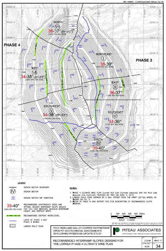
Figure 16-3: Lornex Mine Plan
| October 2025 | Page 16- |
|
|
NI 43-101 Technical Report on Highland Valley Copper Operations British Columbia |

Figure 16-4: Highmont Mine Plan, Expansion
| October 2025 | Page 16- |
|
|
NI 43-101 Technical Report on Highland Valley Copper Operations British Columbia |
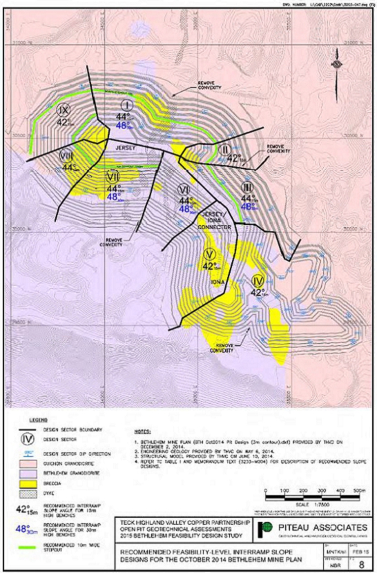
Figure 16-5: Bethlehem Mine Plan
| October 2025 | Page 16- |
|
|
NI 43-101 Technical Report on Highland Valley Copper Operations British Columbia |
Highland Valley is infilled by an overburden stratigraphy of alluvial and glaciolacustrine sediments up to 400 m total thickness. Permeable strata within this sequence include two deep confined aquifers, the Main Aquifer and the Basal Aquifer, and a less well-defined unconfined surficial aquifer, the Upper Aquifers. These aquifers are separated by relatively thick and continuous confining units.
Groundwater flow is controlled by the location, trend, and orientation of faults and jointing relative to the pit slope. Larger-scale fault systems conduct most of the groundwater recharge into the pit slope. Where faults and structural fabric (joints and fault zones) strike normal or oblique to the pit slope, they convey seepage to the pit. Where the surrounding rock mass is sufficiently dilated following mining, these structures and associated rock fabric can be effective drains leading to local reduction in pore pressure.
Surface water from rainfall and snowmelt, and local seepage is currently captured by perimeter collection ditches and in-pit sumps. Depressurization wells are used to control groundwater levels and to reduce seepage where the pit intersects aquifer units. The plan for the LOM is to extend and tie into the current pit water management system.
| 16.3.2 | HIGHMONT PIT |
Bedrock forming the walls of Highmont pit are recharged primarily by direct rainfall and snowmelt. Groundwater flow is through faults and fractures in bedrock which form generally low storage and low hydraulic conductivity pathways. Most flow will occur through the upper 10–20 m deep zone of disturbed and weathered bedrock below the mined slope face. Based on piezometric monitoring in the Highmont pit, bedrock generally depressurizes to a minimum 30 m depth behind the slope both from drainage and unloading from mining. The Waterhole Fault Zone is oriented such that drainage to the face is impeded in the east wall of the pit. Consequently, the fault is assumed to remain saturated except where it daylights on the pit slope. Behind the fault, deeper bedrock is assumed to remain saturated. Modest depressurization is assumed in pit slopes above where the fault is exposed in the slope.
The Highmont pit is on top of a local topographic high point, and therefore minimal surface runoff drains to the pit from surrounding catchments. The new Highmont pit west diversion ditch and Highmont pit east diversion ditch will divert the small natural catchments away from the pit. Other waters will collect in Highmont Creek with eventual conveyance to the Million Gallon Tank for use in processing.
| 16.3.3 | LORNEX PIT |
The rock mass comprising the Lornex pit walls exhibits a moderate permeability, as indicated by the flows produced by horizontal drainholes and wells located around its perimeter. High piezometric heads in piezometers behind the east wall of the pit, and along the southwest and west pit perimeters, indicate the drawdown effects from mine development have not extended very far behind the pit crests. The conceptual groundwater flow model therefore consists of a moderately permeable rock mass near the pit walls, with surrounding rock of generally low permeability. Pit inflow occurs as direct precipitation, seepage from the pit walls and discharge from horizontal drainholes. Pit outflow is comprised of pumped flows from in-pit sumps and pit lake evaporation.
The north–south-striking Lornex Fault and northwest–southeast/northeast–southwest-striking faults are the dominant structures in the pit area and introduce an anisotropy into the rock mass. Structures striking sub-parallel to the slope face can lead to the development of perched groundwater in the upper portions of the slope.
| October 2025 | Page 16- |
|
|
NI 43-101 Technical Report on Highland Valley Copper Operations British Columbia |
| 16.3.4 | BETHLEHEM PITS |
The bedrock hydrology is characterized by fracture-controlled porosity within a multiphase felsic intrusive rock mass. Hydraulic conductivity values are strongly correlated with depth which is assumed to be at least partially due to disturbance from past mining. Hydraulic conductivity results for the Bethlehem, Guichon and Breccia geotechnical units indicate that the latter is slightly more permeable than the former two, and that fault zones are also slightly more permeable. It is interpreted that a combination of fracture density, aperture and connectivity provide the dominant control on hydraulic conductivity in the rock mass below the Bethlehem pits.
Based on historical aerial photographs, it appears that lake levels in the Bethlehem pits are at a state of equilibrium, with evaporative and minor seepage losses in balance with direct precipitation, runoff and groundwater inflows. Data from existing piezometer installations suggest that a downward gradient, either to the regional flow regime or towards seepage faces on the lower pit walls, is expected to be induced in all the pit walls, in response to mine development.
| 16.4 | Mine Designs |
The pit designs described in Section 15.2 and Section 15.3 were divided into phases based on ore prioritization and haulage sequencing (Table 16-3).
16.4.1.1 Mining Method
Drilling and blasting transform the in-situ rock in the pits into fragmented material to facilitate mining. Selective extraction with shovels segregates the ore from waste rock for processing. Conventional or autonomous haul vehicles transport the ore to crushers placed in or adjacent to the actively mined pits. Conveyor systems collect the crushed ore and transfer the ore to the Highland mill. Shovels load the segregated waste rock onto conventional or autonomous haul vehicles for transport and placement onto WRSFs along the perimeter of the active pits.
16.4.1.2 Haul Roads and Ramps
In compliance with British Columbia’s Mines Act, all haul roads have been designed for a minimum 25 m running width to accommodate two-way traffic for the Caterpillar 793 haul truck fleet (8.3 m width). An additional 7 m is incorporated into pit designs to account for a 2.6 m high safety berm constructed from waste material with angle of repose slopes, and a further 3 m is typically allocated for a ditch at the toe of the wall. Roads are designed to a maximum grade of 10%. Roads exterior to the pit, including in WRSFs, are typically designed with an additional 5 m of width and maximum grade of 8% for increased productivity without the negative economic impacts associated with constructing wider, shallower ramps within the pits. All roads inside the site’s main entry gate are operated as left-hand drive.
| 16.5 | Stockpiles |
Stockpiles are discussed in Section 15.6.
| October 2025 | Page 16- |
|
|
NI 43-101 Technical Report on Highland Valley Copper Operations British Columbia |
Table 16-3: Pit Phases
| Pit | Number of Phases in LOM Plan |
Comment |
| Valley | 3 pushbacks and 9 phases |
West Wall Pushback: This single-phase design has been active since 2009. Originally isolated to the western side of the pit, it now also extends along the southern wall and will eventually deepen the pit bottom on all sides. A source of high-quality ore with little waste, it is scheduled to be completed in early 2028. Pushback 1: This design is primarily an expansion to the north and east sides of the existing pit to access the high-quality ore at depth. Phase 1A was designed to focus on the northern half of the pit, stopping before reaching Crusher 5 in order to delay the need to move it. As it progresses, this phase will establish a new, long-term haulage ramp as well as a ramp on which two conveyors will be placed to reach a new site for Crushers 4 and 5 on the northeast wall within this phase. Phase 1A includes buttressing of the 10A geological unit but stops above the 10B unit, which will require more extensive buttressing as part of Phase 1C. Part of the northwestern area of the pit (which mines out part of the existing Jurassic WRSF) is mined to the ultimate pit limit since there is insufficient width for two passes. Much of the northeastern part of Phase 1A is also mined to the ultimate pit limit to make room for the crushers and conveyors, which will only be moved once for this mine plan. Phase 1A is almost entirely waste. Phase 1B is also designed to delay moving the Valley crushers but is in the southwest area of the pit, separate from Phase 1A. Phase 1B begins by rehandling a portion of the Lornex Northwest WRSF, including the current landfill site. As it advances to lower elevations, it avoids digging out the road connecting the Valley open pit to the mine shop and the conveyor systems that run along it. The extent of Phase 1B is largely dictated by the geotechnical need to fully remove the Avalanche lithological unit that exists below. Phase 1B is entirely waste. Phase 1C merges and deepens Phases 1A and 1B. As it begins, it immediately mines through the existing conveyor alignments and so the crushers and conveyors must first be moved to the new location in Phase 1A. Buttressing of the 10A and 10B lithological units with waste rock is required for much of the length of Phase 1C and is scheduled for the early to mid-2030s. Phase 1C advances through large quantities of waste with little ore until fully below the overburden units but then quickly turns to high-grade, low-strip ore. Phase 1D is a continuation of Phase 1C to lower depths but was separated to demonstrate the first of two temporary ramp systems needed to tie Pushback 1 into lower portions of the West Wall Pushback’s ramp, which allow more ore to be included with Pushback 1. Phase 1E is a further advancement of 1C and 1D after the final tie-in to the West Wall ramp. The phase ends as the pit bottom becomes too confined to continue further without the next pushback. Pushback 2: This design includes the second, final pushback of the northern and eastern pit walls, as well as mining the southwestern quadrant of the pit. Phase 2A begins at the highest elevations of the Valley open pit, mining near-surface ore in the southwest. Although this ore is low-grade, its accessibility and low strip ratio make this phase critical to providing mill feed while Pushback 1 is being developed. As such, Phase 2A is started well before the rest of Pushback 2. Phase 2B is a small phase directly below Phase 2A. It completes some of the higher strip ratio areas left behind by Phase 2A. It also establishes a connection between the southwest area and the rest of the pit, which was divided by the mining required to remove the Avalanche unit in Phases 1B and 1C in the southeast. Phase 2C is the remainder of the Valley pit mining. Its highest benches push back the north and east walls created by Pushback 1. After reaching the elevation of the bottom of Phase 2B, it encompasses the full extent of the pit. On the north and east sides, it mines through and then replaces most of the buttressing created for Pushback 1. |
| October 2025 | Page 16- |
|
|
NI 43-101 Technical Report on Highland Valley Copper Operations British Columbia |
| Pit | Number of Phases in LOM Plan |
Comment |
| Lornex | 1 | Limited to a single phase, the last of four that constituted the Lornex Extension permitted in 2011. Mining is currently occurring on the north and west walls of the pit and will extend to the rest of the pit as it deepens below the previous phases. |
| Highmont | 4 | The Highmont pit was last mined in significant quantities in 2016. A large portion of the permitted design was left incomplete in favour of higher quality ore that could obtained from Valley and Lornex. The remaining material is now included in a larger pit design that has been divided into four phases. Phase 1 is the upper benches of the southwest quadrant of the pit which are separated from the rest of the pit because they must be accessed from the surface or via a temporary ramp that will be removed with Phase 3. Phase 2 is the upper benches on the north and east sides of the pit. Phase 3 mines the rest of the pit except for the east wall, accelerating the advance toward the new pit bottom. Phase 4 completes the pit. While initially focused on the east wall, it expands to the full pit as it mines through the ramps used by Phase 3 and extends to depths that could not be reached by the previous phase. |
| Bethlehem | 6 | The phases are divided for haulage purposes and to defer stripping requirements. Phase 1 is focused on mining the high ground on the south side of the pit. Accessing it will require establishing a haul road to connect this area to the existing road on the west side of the pit. Due to the elevation on the southside, Phase 1 must build this road around the Jersey and Iona pit rims before a direct connection can be made by lowering the south wall. Phase 2 uses the new connection to continue lowering the south side with more efficient haulage routes and stops once a flat road between the entrance to the pit and Phase 3 has been created. Phase 3 access low strip, near surface ore to the east of Iona pit. Phase 4 continues the pushback of the south wall as well as the southeast area, around and below Iona pit. Phase 5 is a pushback of the northern half of the Bethlehem pit, ending approximately halfway to the ultimate pit bottom. Phase 6 is the remainder of the pit, focused on reaching the designed pit bottom, below the existing Jersey pit. |
| 16.6 | Waste Rock Storage Facilities |
At the Report effective date, there were 19 WRSFs in the Project area, of which nine are active. The active WRSFs are shown in Figure 16-6. The predominant waste rock types are granite, granodiorite, quartz monzonite, and quartz diorite.
The Lornex North and Lornex Northwest WRSFs are actively being used for Lornex waste. Capacity in the Lornex WRSFs that is not required for Lornex material will be used to store waste rock from the upper benches of Valley Phase 1B.
| October 2025 | Page 16- |
|
|
NI 43-101 Technical Report on Highland Valley Copper Operations British Columbia |
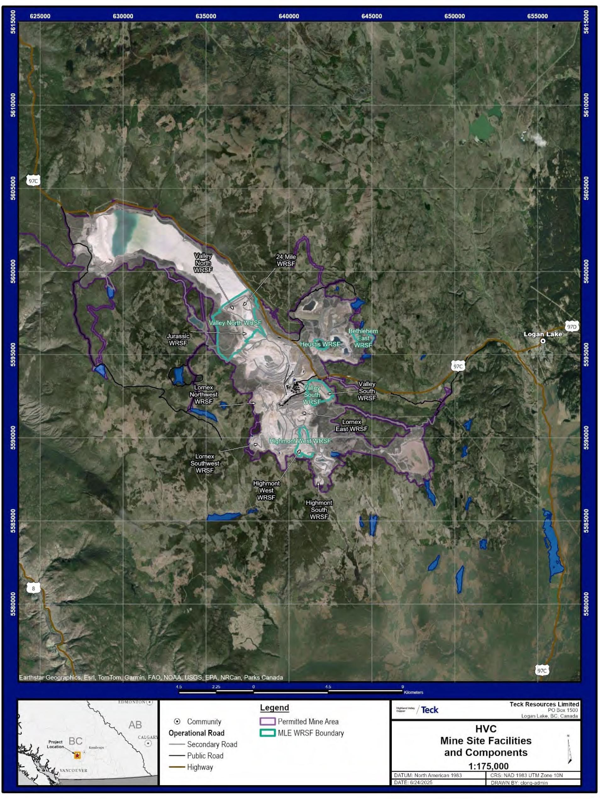
Figure 16-6: WRSF Location Plan
| October 2025 | Page 16- |
|
|
NI 43-101 Technical Report on Highland Valley Copper Operations British Columbia |
Valley waste is actively being hauled to the 24 Mile WRSF, with some loads also being used to construct the H-H Dam. The 24 Mile WRSF and the dam, as well as some of the historical WRSFs in the area, will be integrated into the Valley North WRSF, which will hold most of the waste to be mined in the Valley open pit. Other Valley waste, primarily from the upper, southeast benches of the pit will be used to expand the existing Valley South WRSF.
All Highmont waste will be placed in the Highmont West WRSF, which combines the area of the backfilled West pit with historic Lornex WRSFs. The Highmont West WRSF also covers the current haul road to the Highmont area, which will be raised and relocated a short distance to the east, running along the side of the Highmont West WRSF. The new road is scheduled to be constructed with waste from the upper benches of the Valley pit prior to the reactivation of Highmont mining.
Most Bethlehem waste will be placed in the Bethlehem WRSF, an extension of the historic WRSF east of the Jersey open pit. Additional waste will be used to backfill the Huestis open pit (a substantial portion of which was previously filled) and then continue to build the Huestis WRSF above the former pit. The Iona WRSF will use waste from the final phase of the Bethlehem open pit to backfill the southeast portion of Phases 3 and 4. The three Bethlehem WRSFs have sufficient capacity for most but not all of the Bethlehem open pit waste so the remainder will be hauled to the Valley North WRSF.
When designing WRSFs, each dump lift is designed at the angle of repose (36–37º) to reflect the natural tendency of material to come to a state of rest against existing topography. This design guides the short-term execution of dumping. The overall design dimensions consider long-term reclamation of the dump to the reduced maximum slope angle of up to 24º, which is less erosion prone and has been demonstrated to support revegetation that further stabilizes the reclamation covers.
| 16.7 | Infrastructure |
Mine infrastructure requirements for the LOM plan are discussed in Section 18.1.
| 16.8 | Life-Of-Mine Plan |
The remaining mine life is approximately 21 years, ending in March 2046 and will be followed by reclamation activities. Figure 16-7 provides the material movement over the LOM. Figure 16-8 shows the mill feed plan by source.
About 2,581 Mt will be mined from the pits and 3 Mt will be re-handled from the existing long-term stockpile. A total of 1,102 Mt will be processed by the mill, including 1,073 Mt hauled directly from the pits to the primary crushers, the existing stockpile, and 26 Mt of Valley ore stockpiled in future years and delivered to the crushers in 2046. About 1,752 Mt of waste rock and overburden will be mined, consisting mostly of in-situ material but also large, planned quantities in existing and future waste rock buttresses in the Valley pit and existing WRSFs in the Valley and Bethlehem pits. These quantities do not include smaller quantities of rehandled material anticipated as a part of routine operations.
| October 2025 | Page 16- |
|
|
NI 43-101 Technical Report on Highland Valley Copper Operations British Columbia |
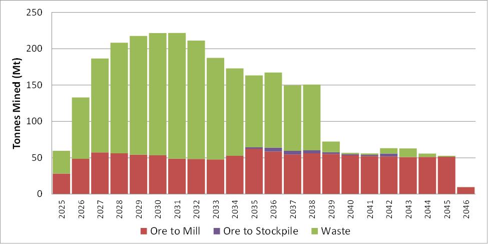
Note: Figure prepared by Teck, 2025. 2025 numbers are forecast partial year, not full year actual + forecast.
Figure 16-7: LOM Production Plan by Destination
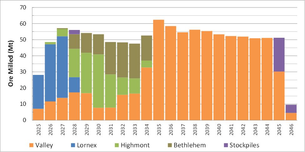
Note: Figure prepared by Teck, 2025. 2025 numbers are forecast partial year, not full year actual + forecast.
Figure 16-8: LOM Mill Feed by Source
| October 2025 | Page 16- |
|
|
NI 43-101 Technical Report on Highland Valley Copper Operations British Columbia |
| 16.9 | Blasting and Explosives |
Drilling and blasting requirements for both current operations and the LOM plan are estimated on a bench-by-bench basis using parameters associated with current operational practice. This includes trim and buffer blasting along the perimeter of final walls and drill hole spacing determined by pit and material classification. It is assumed the only overburden that must be blasted is the 246 Mt belonging to the till unit in the Valley pit. Pre-shear blasting is planned for amenable sections of the final walls in the Valley, Highmont, and Bethlehem open pits as well as intermediate walls created by Valley’s West Wall Pushback and Pushback 1.
A portion of the rock with a blastability index of 20 or lower (identified in the resource models) was classified as “free dig” and is not scheduled for blasting, although all ore is still drilled for assaying purposes. A significant portion of Lornex mining falls within the free dig category. Within Valley, free dig material is typically in the upper southwest benches and in the vicinity of the Lornex Fault on the east wall. Very little Highmont and no Bethlehem mining was modelled as free dig.
Frost blasting was accounted for by adding approximately 21 shallow holes per 100 production holes. Drill hours were inflated by 0.5% above the calculated requirements to account for re-drilling of collapsed holes.
Explosives and accessories were estimated as per the current operation, including the use of sodium nitrate in ore blasts to augment the ammonium nitrate common to all blasts.
| 16.10 | Grade Control |
Grade control drilling is described in Section 10.7, and grade control sampling in Section 11.1.4.
| 16.11 | Equipment |
The peak production equipment requirements are summarized in Table 16-4.
Truck hours were driven directly by the scheduled tonnages, their associated haul times, and payloads. Shovels were assigned to specific phases as part of the scheduling software. All truck and shovel hour requirements included an allowance for rehandled tonnages, which was 2% of in-situ rock and 6% of overburden. Truck requirements were also inflated to account for an additional rehandle volume of 5% of the ore tonnage, based on short-term stockpiling practices employed to optimize equipment utilization. Major rehandling projects (the digging of the existing Valley buttresses and the replacements constructed with the first expansion pushback as well as backfilled areas of Bethlehem) had their tonnages included in the in-situ volumes to simplify the scheduling process.
Drilling hours were the product of mining quantities and an extensive calculation of meterage requirements and drilling rates based on material type and blasting fragmentation requirements, including wall control blasting.
Support equipment (track dozers, rubber tire dozers, graders, front-end loaders) needs were calculated from historically correlated ratios to shovel hours, truck hours, and tonnages. For all production equipment, the calculated hours were translated into fleet sizes by using operations-approved utilization values.
| October 2025 | Page 16- |
|
|
NI 43-101 Technical Report on Highland Valley Copper Operations British Columbia |
Table 16-4: Peak Production Equipment Requirements
| Area | Equipment Type | Number Required |
| Shovels | P&H 2800 | 4 |
| BI 495HR | 2 | |
| P&H 4100 | 5 | |
| Trucks | Conventional Cat 793 | 23 |
| Automated Cat 793 | 87 | |
| Combined Fleet | 87 | |
| Drills | BI 49R | 10 |
| Front-end loaders | Letourneau L1850 | 3 |
| Komatsu WA600 | 2 | |
| Dozers | Cat D10 | 18 |
| Cat 844 | 4 | |
| Graders | Cat 16 | 2 |
| Cat 24 | 8 |
| October 2025 | Page 16- |
|
|
NI 43-101 Technical Report on Highland Valley Copper Operations British Columbia |
17 RECOVERY METHODS
| 17.1 | Introduction |
The mill is based on a robust metallurgical flowsheet designed for optimum recovery with minimum operating costs. The flowsheet is based upon unit operations that are well proven in industry. The mill operates 24 hours per day, 365 days per year.
The processing circuit consists of crushers to size feed and overland conveyors to transfer feed, and milling facilities to produce the final concentrate product.
| 17.2 | Process Upgrades |
The project to extend the mine life assumes an increase in overall mill throughput, and the addition and modification of equipment within the existing mill. Modifications and changes are planned to include:
| ● | Modification of some conveyors, modifications to pump boxes and process lines as needed, modifications to existing flotation area process water systems (strained and unstrained) and air system; |
| ● | Relocation of some conveyors and primary crushers; |
| ● | Replacement of existing shiftable rockbox, D-line discharge system, H-H tailings pumphouse; L-L booster pump station, and reclaim barges for the Highland TSF; |
| ● | Conversion of existing D line autogenous grind (AG) mill to a semi-autogenous grind (SAG) mill; |
| ● | Addition of conveyors and tramp metal removal systems, a new C3 tertiary mill and cyclones, bulk flotation regrind mill to be installed in parallel to the existing regrind mill, bulk flotation regrind cyclones, and water management system; |
| ● | Reconfiguration of bulk cleaner circuit process flows |
| 17.3 | Process Flow Sheet |
The process flowsheet is provided in Figure 17-1 to Figure 17-5. Modifications required to support the LOM plan are shown in the schematic included as Figure 17-4 and Figure 17-5.
| 17.4 | Plant Design |
Process design criteria are summarized in Table 17-1, and the forecast throughput by grinding line is provided in Table 17-2.
| October 2025 | Page 17- |
|
|
NI 43-101 Technical Report on Highland Valley Copper Operations British Columbia |

Figure 17-1: Current Conveyor Flow Sheet
| October 2025 | Page 17- |
|
|
NI 43-101 Technical Report on Highland Valley Copper Operations British Columbia |
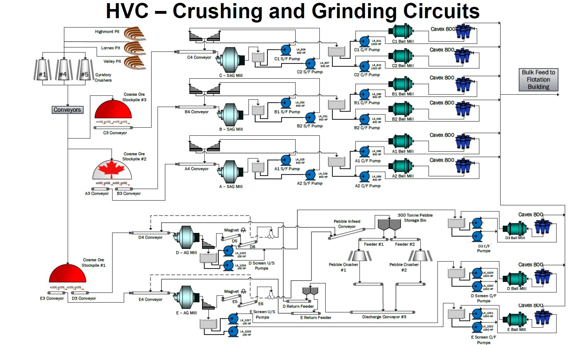
Note: Figure prepared by Teck, 2024.
Figure 17-2: Current Crushing and Grinding Circuit
| October 2025 | Page 17- |
|
|
NI 43-101 Technical Report on Highland Valley Copper Operations British Columbia |
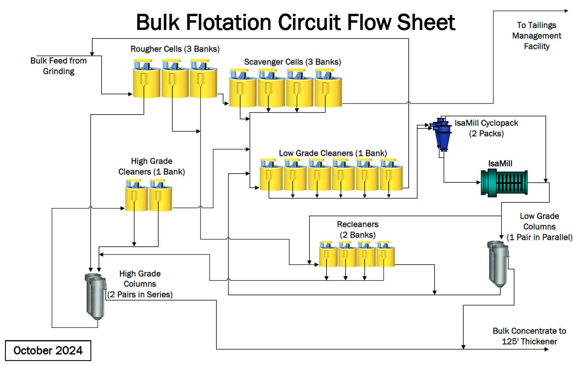
Note: Figure prepared by Teck, 2024.
Figure 17-3: Current Bulk Flotation Circuit
| October 2025 | Page 17- |
|
|
NI 43-101 Technical Report on Highland Valley Copper Operations British Columbia |
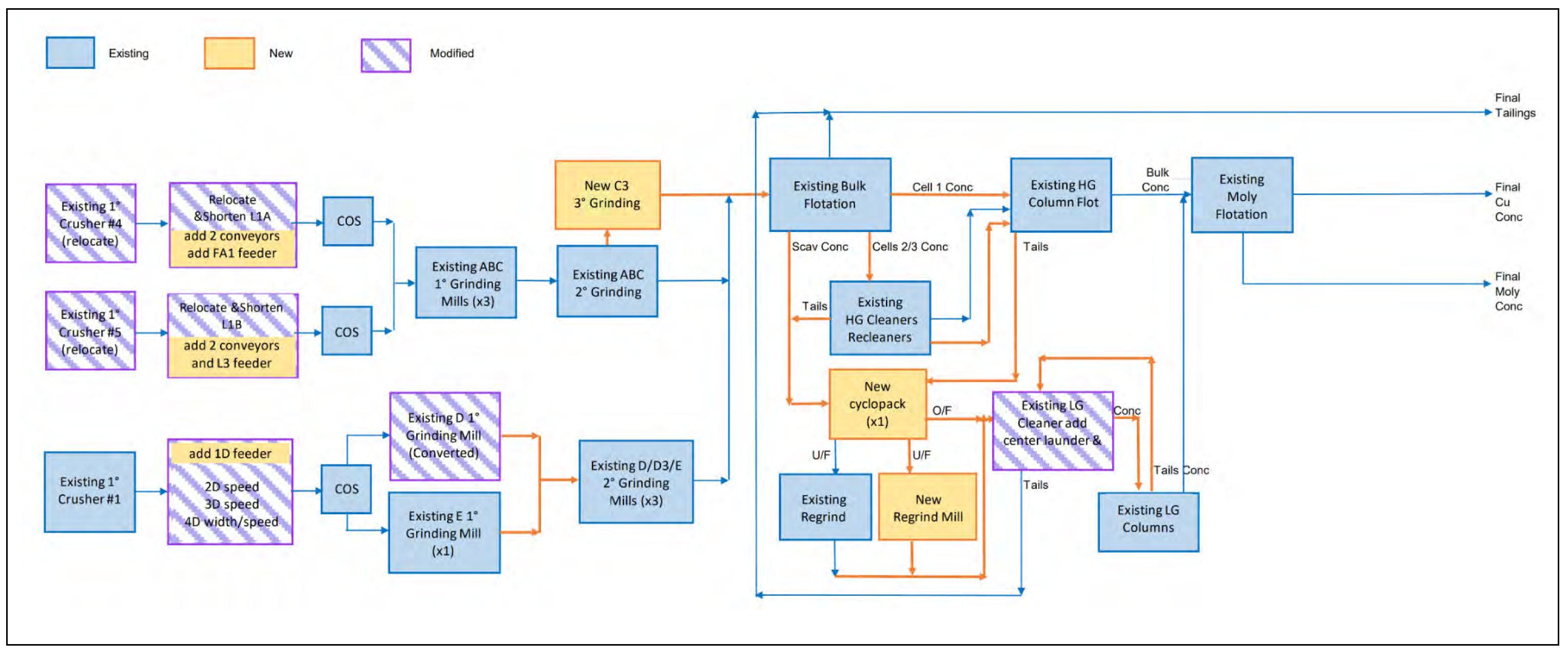
Note: Figure prepared by Teck, 2023.
Figure 17-4: Modifications Required for LOM Plan
| October 2025 | Page 17- |
|
|
NI 43-101 Technical Report on Highland Valley Copper Operations British Columbia |
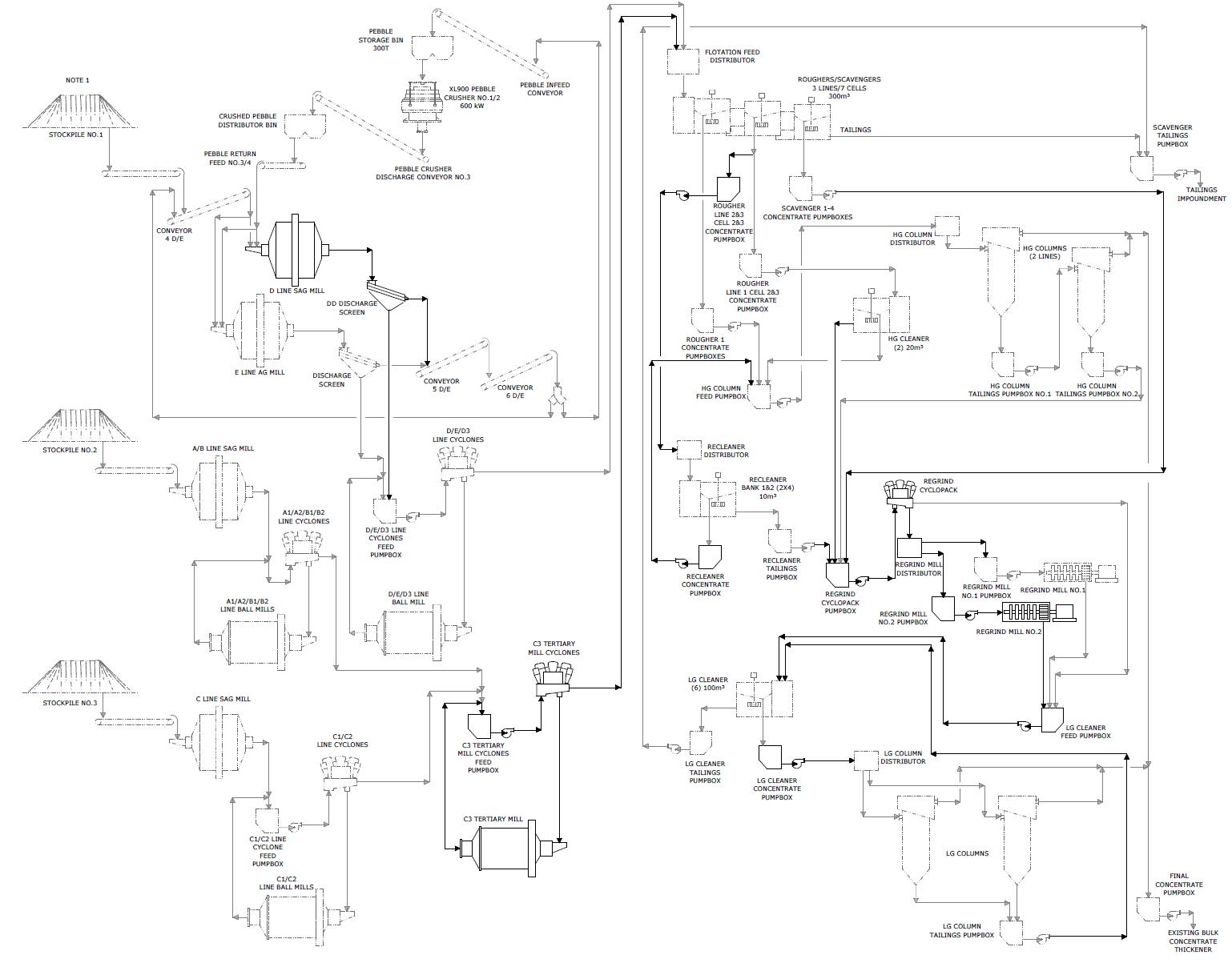
Note: Figure prepared by Teck, 2023. Dashed lines indicate existing circuit. Solid lines indicate new or modified circuit.
Figure 17-5: Process Flow Sheet with Modifications Required for LOM Plan
| October 2025 | Page 17- |
|
|
NI 43-101 Technical Report on Highland Valley Copper Operations British Columbia |
Table 17-1: Mill Design Criteria
| Production | Units | Value |
| Annual throughput | t/a | 58,993,125 |
| Nameplate throughput | t/d | 161,625 |
| Runtime (excluding filtration) | % | 95.42 |
| Plant runtime (filtration) | % | 70 |
| Operating schedule | h/d | 24 |
| Operating schedule | d/a | 365 |
| Operating hours | h/a | 8,359 |
Table 17-2: Mill Throughput by Grinding Line
| Line | Nominal (t/h) |
Nameplate (t/d) |
Design (t/h) |
| All Lines | 7,058 | 161,625 | 7,764 |
| A | 1,182 | 27,069 | 1,300 |
| B | 1,182 | 27,069 | 1,300 |
| C | 1,653 | 37,855 | 1,818 |
| D | 2,170 | 49,692 | 2,387 |
| E | 871 | 19,941 | 958 |
| 17.4.1 | CRUSHING AND MATERIAL HANDLING |
Primary crushing buildings 4 and 5 are currently located east of the Valley pit. The crushed ore is transported to any of the three stockpiles by a system of overland conveyors. Currently, conveyor 2D feeds material onto stockpile 1 and conveyor 2-2 feeds materials onto stockpile 2. For increased material distribution flexibility to accommodate the feed into the D-line SAG mill (converted from an autogenous grinding mill to a SAG mill as part of the initial scope), proportional feeders are required at the head ends of conveyors L3 and 1D. This will allow for more control of material distribution between stockpiles 1 and 2. Conveyor 3D and 4D need to increase in speed to accommodate more feed into the new converted SAG mill. Finally, two new self-cleaning tramp metal magnetic removal systems are required on conveyor 6D to remove tramp metal once the D-line AG mill is converted into a SAG mill.
Crushers 4 and 5 will be moved to the northeast side of the Valley pit in approximately 2028. At that point, new conveyors L1A and L1B will be required at the new primary crusher location and two new overland conveyors A1 and B1 will be added. Conveyor A1 will transport ore to a new proportional feeder FA1 and conveyor B1 to existing feeder F3.
| October 2025 | Page 17- |
|
|
NI 43-101 Technical Report on Highland Valley Copper Operations British Columbia |
| 17.4.2 | GRINDING |
The existing facility currently stores crushed ROM ore on three stockpiles that feed the existing grinding circuits, lines A, B, C, D, and E. Grinding lines A and B are fed from stockpile 2; line C is fed from stockpile 3, and lines D and E are fed from stockpile 1 (Table 17-3).
Currently, grinding lines A, B, and C each consist of a SAG mill for primary grinding and a pair of ball mills for secondary grinding arranged in a parallel configuration, with each ball mill in closed circuit with a cyclone cluster. The cyclone overflow from each secondary grinding circuit reports to the bulk flotation circuit.
Equipment in grinding lines A, B and C will remain as per the current operation. However, as part of the initial modifications, lines A, B and C secondary grinding cyclone overflow will be combined and rerouted to feed a new ball mill circuit with a new 12.0 MW C3 tertiary mill in closed circuit with a cyclone cluster. The C3 cyclone overflow will report to the bulk flotation circuit.
Currently, grinding lines D and E each consist of an autogenous grind (AG) mill for primary grinding. Pebbles generated in the autogenous grinding mills are conveyed a separate pebble crushing building that contains two pebble crushers in parallel. Crushed pebbles are returned to the autogenous grinding mills for further grinding. Products from the two autogenous grinding mills are split between three ball mills operating in parallel (D/E/D3). Each ball mill is in closed circuit with a cyclone cluster. The cyclone cluster from each secondary grinding circuit currently reports to the bulk flotation circuit.
Equipment in grinding line E will remain as per the current operation. However, as part of the initial modifications, the existing D-line autogenous grinding mill will be converted to a 10.5 MW SAG mill. The D and E primary mill products will continue to be fed to the existing D, E, and D3 ball mills, with ball mill cyclone overflow products reporting to the bulk flotation stage.
The following mechanical equipment will be modified to increase grinding capacity:
| ● | D-line autogenous grind mill converted to 10,500 kW SAG mill; |
| ● | D-line SAG mill screen U/S pump box; |
| ● | D-line cyclone feed pump box; |
| ● | D3 cyclone feed pump box. |
The following mechanical equipment will be added/replaced as part of the initial scope to increase grinding capacity:
| ● | D-line SAG mill discharge screen; |
| ● | D-line screen undersize pumps; |
| ● | Conveyor 6D tramp metal removal system; |
| ● | C3 tertiary ball mill; |
| ● | C3 tertiary mill cyclones; |
C3 tertiary mill cyclone feed pump box and pump.
| October 2025 | Page 17- |
|
|
NI 43-101 Technical Report on Highland Valley Copper Operations British Columbia |
Table 17-3: Grinding Circuit
| Feed Source | Stockpile 1 | Stockpile 2 | Stockpile 3 | |
| Grinding lines | D and E lines | A and B lines | C line | |
| Primary grinding | D-line SAG mill, 34 ft dia. x 16 ft high; 10,500 kW | E Line AG mill, 34 dia. x 16ft high; 6,572 kW | SAG mills, each 32 ft dia. x 15.5 ft high; 6,860 kW | SAG mill, 34 ft dia. x 16 ft high; 9,321 kW |
| Pebble crushing | Yes, 2 x 900 hp crushers | No | ||
| Secondary grinding |
D ball mill, 16.5 ft dia. x 29.4 ft high; 4,100 kW D3 ball mill, 21 ft dia. x 24.1 ft high; 5,800 kW |
E ball mill, 16.5 ft dia. x 29.4 ft high; 4,100 kW | Ball mills, two per line, each 16.5 ft dia. x 23 ft high; 3,380 kW motor | Ball mills, two per line, each 16.5 ft dia. x 26.5 ft high; 3,720 kW motor (C1), 4,660 kW motor (C2) |
| Tertiary grinding | No | Yes, ball mill. One per combined A, B, and C line. Each 24.7 ft dia. x 34.1 ft high, 12,000 kW | ||
17.4.2.1 Grinding Line A
Table 17-4 summarizes the key process design parameters.
The Line A grinding circuit is an existing circuit and consists of a conventional SAG mill and two ball mills (A1 and A2). The grinding circuit is fed from stockpile 2 and is designed with an overall system run-time of 95.42% with a nominal throughput of 1,182 t/h solids.
Steel balls used for SAG mill grinding media are fed to the SAG mill together with coarse ore as per the existing configuration. A ball charge of about 11% by volume is maintained with a maximum allowable operational load of 22%. The 32 ft diameter SAG mill with an effective grinding length (EGL) of 15.5 ft is driven by twin mill drives at 3,430 kW each, equipped with adjustable speed drive. Process water is added to the feed chute to achieve about 70% solids concentration in the mill. Lime slurry is added on a pH control loop into the SAG mill to achieve the target pH of 10.
Crushed ore is ground and screened from an 80% passing feed size of 88 mm in SAG mill feed to an 80% passing transfer size of 2.7 mm. Ground ore from the SAG mill is pumped to a screen with a 19 mm aperture. Screen oversize is returned to the SAG mill, with a pebble recirculating load of 11%. The undersize product from the discharge screen reports to the two ball mill circuits, A1/A2.
| October 2025 | Page 17- |
|
|
NI 43-101 Technical Report on Highland Valley Copper Operations British Columbia |
Table 17-4: Grinding Line Process Parameters
| Line | Parameter | Unit | Value |
| A-line | Circuit nominal throughput | t/h | 1,812 |
| SAG mill dimensions | feet | 32 dia. x 15.5 EGL | |
| SAG mill feed 80% passing size | F80 mm | 88 | |
| SAG mill and screening transfer particle size | T80 mm | 2.7 | |
| SAG mill solids content | % w/w | 67.8 | |
| SAG mill ball charge | % | 11 | |
| SAG mill maximum operational load | % | 22 | |
| A ball mill dimensions | feet | 16.5 dia. x 23 EGL | |
| A ball mill circulating load | % | 321 | |
| A ball mill solids content | % w/w | 74 | |
| Cyclone feed solids content | % w/w | 62 | |
| Cyclone underflow solids content | % w/w | 81 | |
| Cyclone overflow solids content | % w/w | 35 | |
| Cyclone overflow 80% passing size | μm | 423 | |
| B-line | Circuit nominal throughput | t/h | 1,812 |
| SAG mill dimensions | feet | 32 dia. x 15.5 EGL | |
| SAG mill feed 80% passing size | F80 mm | 88.7 | |
| SAG mill and screening transfer particle size | T80 mm | 2.6 | |
| SAG mill solids content | % w/w | 71.3 | |
| SAG mill ball charge | % | 11 | |
| SAG mill maximum operational load | % | 21.9 | |
| B ball mill dimensions | feet | 16.5 dia. x 23 EGL | |
| B ball mill circulating load | % | 292 | |
| B ball mill solids content | % w/w | 74 | |
| Cyclone feed solids content | % w/w | 59.7 | |
| Cyclone underflow solids content | % w/w | 78.6 | |
| Cyclone overflow solids content | % w/w | 35 | |
| Cyclone overflow 80% passing size | μm | 362 | |
| C-line | Circuit nominal throughput | t/h | 1,653 |
| SAG mill dimensions | feet | 34 dia. x 16 EGL | |
| SAG mill feed 80% passing size | F80 mm | 88 | |
| SAG mill and screening transfer particle size | T80 mm | 2.8 | |
| SAG mill solids content | % w/w | 66.5 | |
| SAG mill ball charge | % | 12 | |
| SAG mill maximum operational load | % | 28.8 | |
| C ball mill dimensions | feet | 16.5 dia. x 26.5 EGL |
| October 2025 | Page 17- |
|
|
NI 43-101 Technical Report on Highland Valley Copper Operations British Columbia |
| Line | Parameter | Unit | Value |
| C ball mill circulating load | % | 237 | |
| C ball mill solids content | % w/w | 75.5 | |
| Cyclone feed solids content | % w/w | 66.5 | |
| Cyclone underflow solids content | % w/w | 81.8 | |
| Cyclone overflow solids content | % w/w | 46 | |
| Cyclone overflow 80% passing size | μm | 486 | |
| D-line | Circuit nominal throughput | t/h | 2,170 |
| SAG mill dimensions | feet | 34 dia. x 16 EGL | |
| SAG mill feed 80% passing size | F80 mm | 88.1 | |
| SAG mill and screening transfer particle size | T80 mm | 3.59 | |
| SAG mill solids content | % w/w | 71 | |
| SAG mill ball charge | % | 14 | |
| SAG mill maximum operational load | % | 27.4 | |
| D ball mill dimensions | feet | 16.5 dia. x 29.4 EGL | |
| D ball mill circulating load | % | 131 | |
| D ball mill solids content | % w/w | 74 | |
| D ball mill cyclone feed solids content | % w/w | 57.9 | |
| D ball mill cyclone underflow solids content | % w/w | 79.0 | |
| D ball mill cyclone overflow solids content | % w/w | 43.1 | |
| D ball mill cyclone overflow 80% passing size | μm | 336 | |
| D3 ball mill dimensions | feet | 21 dia. x 24.1 EGL | |
| D3 ball mill circulating load | % | 127 | |
| D3 ball mill solids content | % w/w | 74 | |
| D3 ball mill cyclone feed solids content | % w/w | 59.4 | |
| D3 ball mill cyclone underflow solids content | % w/w | 79.1 | |
| D3 ball mill cyclone overflow solids content | % w/w | 45.2 | |
| D3 ball mill cyclone overflow 80% passing size | μm | 363 | |
| E-line | Circuit nominal throughput | t/h | 871 |
| AG mill dimensions | feet | 34 dia. x 16 EGL | |
| AG mill feed 80% passing size | F80 mm | 88.1 | |
| AG mill and screening transfer particle size | T80 mm | 2.17 | |
| AG mill solids content | % w/w | 71 | |
| AG mill ball charge | % | 0 | |
| AG mill maximum operational load | % | 27.9 | |
| E ball mill dimensions | feet | 16.5 dia. x 29 EGL | |
| E ball mill circulating load | % | 131 | |
| E ball mill solids content | % w/w | 74 |
| October 2025 | Page 17- |
|
|
NI 43-101 Technical Report on Highland Valley Copper Operations British Columbia |
| Line | Parameter | Unit | Value |
| Cyclone feed solids content | % w/w | 57.9 | |
| Cyclone underflow solids content | % w/w | 79.0 | |
| Cyclone overflow solids content | % w/w | 43.1 | |
| Cyclone overflow 80% passing size | μm | 336 |
Each 16.5 ft ball mill has an EGL of 23 ft and is driven by a single pinion adjustable speed motor. The ball mills are fed underflow from a cyclone cluster of three online and three spare 800 mm cyclones operating in a closed circuit with the mill with a 321% recirculating load. In addition, each mill receives process water, pine oil (frother), SIX (collector), PAX (collector), and grinding media. The mill solids contents are maintained to 74% by weight. Ball mill grinding media is transferred as per the existing configuration.
Product from each ball mill flows to a dedicated cyclone feed pump box, which also receives fresh feed from the SAG screen undersize and process water for dilution. Contents of the cyclone feed pump box are diluted to 62% solids by weight and are pumped via a horizontal centrifugal slurry pump to the corresponding cyclone cluster. Cyclone overflow with an 80% passing size of 423 μm flows by gravity to the tertiary mill circuit, and cyclone underflow is returned to the feed spout of the ball mill. Cyclone underflow and overflow solids content is maintained at approximately 81% by weight 35% solids by weight, respectively.
17.4.2.2 Grinding Line B
Line B grinding circuit equipment is existing and configured as per Line A consisting of a SAG mill and two ball mills (B1 and B2). The grinding circuit is fed from stockpile 2 and is designed with an overall system runtime of 95.42% with a nominal throughput of 1,182 t/h solids.
Table 17-4 summarized the key process design parameters.
17.4.2.3 Grinding Line C
The existing grinding line C equipment is configured similar to grinding line A, but with larger SAG and ball mills. The grinding circuit is fed from stockpile 3 and is designed with an overall system run-time of 95.42% with a nominal throughput of 1,653 t/h solids.
Table 17-4 summarized the key process design parameters.
17.4.2.4 C3 Tertiary Mill
The cyclone overflow streams of the existing A1, A2, B1, B2, C1, and C2 secondary ball mills will be combined in a new pump box (C3 cyclone feed pump box) and will report to a new C3 tertiary mill circuit for further size reduction. The C3 tertiary mill is a ball mill designed with an overall run-time of 95.42% and a nominal throughput of 4,017 t/h solids. It will be configured in a closed circuit with a cyclone pack. Cyclone overflow will report to rougher flotation independently along with the cyclone overflow from grinding lines D and E.
| October 2025 | Page 17- |
|
|
NI 43-101 Technical Report on Highland Valley Copper Operations British Columbia |
The tertiary grinding 24.7 ft diameter ball mill will have an EGL of 34.1 ft and be driven by 2 x 6,000 kW (12,000 kW total) dual pinion adjustable speed motors. The mill will be fed underflow from a cyclone cluster of 12 online and two spare 800 mm cyclones operating in a closed circuit with the mill with a 103% recirculating load. In addition, the mill will receive process water, pine oil, SIX, PAX, and grinding media. The mill solids contents will be maintained to 74% by weight. Grinding media will be transferred from a new ball feeder by new buckets and will be configured as per the existing system for the secondary grinding mills.
Product from the tertiary grinding mill will flow to a cyclone feed pump box, which will also receive fresh feed from cyclone overflows of grinding lines A, B, and C, and process water for dilution. Contents of the cyclone feed pump box will be diluted to 50% solids by weight and pumped via a horizontal centrifugal slurry pump to the cyclone cluster.
Cyclone overflow with an 80% passing size of 226 µm will flow by gravity to the rougher flotation circuit, and cyclone underflow will be returned to the feed spout of the tertiary grinding mill. Cyclone underflow and overflow solids content will be maintained at approximately 75% by weight and 37% solids by weight, respectively.
17.4.2.5 Grinding Line D
Existing line D grinding circuit consists of a primary grinding mill, converted to operate as a 10,500 kW SAG mill from the current AG mill, a pebble crushing circuit and three ball mills (D, E and D3) which are shared with line E grinding circuit. The grinding circuit is fed from stockpile 1 and is designed with an overall system run-time of 95.42% with a nominal throughput of 2,170 t/h solids.
Table 17-4 summarized the key process design parameters.
Steel balls used for SAG mill grinding media are fed to the SAG mill together with coarse ore via a refurbished ball charging system. A ball charge of about 14% by volume is maintained with a maximum allowable operational load of 27.4%. The 34 ft diameter SAG mill with an EGL of 16 ft will be driven by 2 x 5,250 kW (10,500 kW total) dual pinion adjustable speed motors. Process water is added to the feed chute to achieve about 71% solids concentration in the mill. Lime slurry is added on a pH control loop into the SAG mill to achieve the target pH of 10.
Crushed ore is ground and screened from an 80% passing feed size of 88.1 mm in SAG mill feed to an 80% passing transfer size of 3.59 mm. Ground ore from the SAG mill discharges to a new screen followed with a 19 mm aperture. Screen oversize discharges to a pebble crushing circuit with a pebble recirculating load of 14.7%.
The undersize product from the discharge screen will report to a modified pump box from where it will be pumped by new horizontal centrifugal pumps to a modified distributor. The distributor also accepts the screen undersize discharge from the E-line AG mill. The distributor distributes material to the three ball mill circuits, D, D3, and E.
The D ball mill has a diameter of 16.5 ft and an EGL of 29 ft that is driven by a 4,101 kW single pinion drive. The D ball mill is fed underflow from a cyclone cluster of three online and three spare 800 mm cyclones operating in a closed circuit with the mill with a 131% recirculating load.
| October 2025 | Page 17- |
|
|
NI 43-101 Technical Report on Highland Valley Copper Operations British Columbia |
The D3 ball mill has a diameter of 21 ft and an EGL of 24.1 ft that is driven by a 5,850 kW single pinion drive. The D3 ball mill is fed underflow from a cyclone cluster of four online and three spare 800 mm cyclones operating in a closed circuit with the mill with a 127% recirculating load.
In addition, each mill receives process water, pine oil, PAX, SIX, and grinding media. The mill solids contents are maintained to 74% by weight. Ball mill grinding media is transferred as per the existing configuration.
Product from each ball mill flows to a dedicated cyclone feed pump box, which also receives fresh feed from the splitter box (primary mill screen undersize) and process water for dilution. Contents of the cyclone feed pump box are diluted to 57.9% solids by weight for the D ball mill and 59.4% for the D3 ball mill. Feed is pumped via a horizontal centrifugal slurry pump to the corresponding cyclone cluster.
Cyclone overflow with an 80% passing size for the D and D3 ball mills of 336 µm and 363 µm, respectively, flows by gravity to the flotation circuit; cyclone underflow is returned to the feed spout of the corresponding ball mill. Cyclone underflow solids content is maintained at approximately 79% by weight for D ball mill and 79.1% by weight for D3 ball mill. Cyclone overflow solids content is maintained at 43.1% and 45.2% solids by weight, respectively, for the D and D3 circuits. The D line cyclone overflow will be a nominal 850 t/h, while the D3 cyclone overflow will be a nominal 1,341 t/h.
17.4.2.6 Grinding Line E
The existing grinding line E circuit consists of primary autogenous grinding, pebble crushing, and a single ball mill (E). The downstream ball milling circuit consisting of the D, E, and D3 mills is shared with line D grinding.
The grinding circuit is fed from stockpile1 and is designed with an overall system run-time of 95.42% with a nominal throughput of 871 t/h solids.
Modifications to this circuit are limited to the installation of level instrument brackets on the D and E line cyclone feed pump boxes and D3 cyclone feed pump box suction nozzle enlargement. Pipeline replacement from the D and E line splitter box is underway.
The E-line cyclone overflow will be a nominal 850 t/h.
Table 17-4 summarized the key process design parameters.
| 17.4.3 | FLOTATION AND REGRIND |
Currently, there are three rows of rougher/scavenger bulk flotation cells, where the rougher 1 concentrate from each line reports to a pair of high-grade columns. Rougher 2 and 3 concentrate from each line reports to two rows of recleaner cells. The scavenger concentrate reports to six low-grade cleaners.
In the high-grade columns, the concentrate forms part of the final bulk concentrate, while the tailings goes to the high-grade cleaners. In the high-grade cleaners, the concentrate reports to the high-grade columns, while the tailings reports to the low-grade cleaners. In the recleaners, the concentrate reports to the high-grade columns, while the tailings reports to the low-grade cleaners. In the low-grade cleaners, the concentrate reports to a regrind circuit, while the tailings recycles back to the rougher/scavenger flotation feed. The regrind product is split three ways, with two parts reporting to a pair of low-grade columns in parallel and one part reporting to two rows of recleaner cells. In the low-grade columns the concentrate forms part of the final bulk concentrate, while the tailings goes back to the low-grade cleaners.
| October 2025 | Page 17- |
|
|
NI 43-101 Technical Report on Highland Valley Copper Operations British Columbia |
The existing flotation and regrind circuits will require some additions and modifications. The flotation cleaner circuits will be reconfigured and operate where there are still three rows of rougher/scavenger bulk flotation cells, where the rougher 1 concentrate from each line continues to report to a pair of high-grade columns. Rougher 2 and 3 concentrate from each line will be split, and will report to either the high-grade cleaners or the recleaners. The recleaners will be repurposed to perform the same function as the high-grade cleaners. The scavengers will report to the regrind circuit, which will contain an additional regrind mill.
In the high-grade columns, the concentrate will form part of the final bulk concentrate, while the tailings will report to the regrind circuit. In the high-grade cleaners and recleaners, the concentrate will report to the high-grade columns, while the tailings will report to the regrind circuit. The regrind circuit discharge will report to the existing low-grade cleaners. In the low-grade cleaners, the concentrate will feed the two existing low-grade columns, while the tailings will report to the scavenger tailings pump box during normal operation (with the option of recycling back to the rougher/scavenger flotation feed).
In the low-grade columns, the concentrate will form part of the final bulk concentrate, while the tailings will return to the low-grade cleaner cells.
The following key mechanical equipment will be replaced or modified:
| ● | Line 1, 2 and 3 scavenger flotation cells; |
| ● | Multiple rougher/scavenger concentrate pump boxes and pumps; |
| ● | Scavenger tailings pumps 1 to 4; |
| ● | Regrind cyclone feed pumps 1 and 2; |
| ● | Twin the existing regrind mill; |
| ● | Regrind mill cyclones; |
| ● | Low-grade cleaners feed pumps 1 and 2. |
| 17.4.4 | ROUGHER AND SCAVENGER FLOTATION |
The combined feed to the rougher flotation circuit from all grinding lines will be 7,058 t/h.
The existing rougher flotation circuit consists of three lines, with the existing distributor directing approximately 2,353 t/h solids to each line. Feed to the rougher flotation circuit will have a solids content of approximately 35% by weight and an 80% passing particle size of about 278 µm to all flotation lines. Feed copper grade to each line is approximately 0.3% Cu and each line will have an overall mass recovery of about 4.0%.
| October 2025 | Page 17- |
|
|
NI 43-101 Technical Report on Highland Valley Copper Operations British Columbia |
All three lines are configured as seven 300 m3 forced-air tank cells with the first three cells of each row functioning as rougher cells and the remaining four as scavenger cells.
Concentrate from the first cell (R1) of each row is high-grade concentrate with a cell mass recovery of 1.12% of feed and a copper concentrate grade of approximately 21.41% Cu. Concentrate from the second and third rougher cells (R2 and R3) is low-grade concentrate with a cell mass recovery of about 0.90% of feed and a copper concentrate grade of approximately 3.68% Cu. Concentrate from the scavenger cells is low-grade concentrate with a cell mass recovery of about 1.98% of the feed and a copper concentrate grade of approximately 0.97% Cu.
Line 1 has its own R1, R2, and R3, and scavenger concentrate pump boxes, while lines 2 and 3 share R1, R2, and R3, and scavenger concentrate pump boxes for transport.
The R1 concentrate from each flotation line is pumped to the high-grade column cells via existing/modified pump boxes and horizontal slurry pumps. In lines 2/3, the R1 concentrate pipes from the cells to the pump box are increased in size. The line 2/3 rougher 1 concentrate pump box will be modified with a bolted-on top piece. The line 2/3 rougher 1 concentrate pumps will be replaced with new adjustable speed drive-driven pumps; the existing motors are suitable. R2 and R3 concentrate from line 1 is transported to the high-grade cleaners via existing pump box and pumps. The pump discharge pipeline will be increased in size. R2 and R3 concentrate from lines 2 and 3 reports to the modified existing pump box from which it is transported to the recleaners via two new (one operating, one standby) adjustable speed drive-driven horizontal slurry pumps.
The pump box will have its overflow box and downcomer modified and pump suction nozzles increased in size. The pump suction and discharge pipes will be replaced with larger diameter pipes. The existing low-grade sampler in this line will also be replaced. Lime slurry will be added to this pump box, allowing for an increase in pH to approximately 11 in the recleaners as they perform the same function as the high-grade cleaners (which also have an existing lime addition point).
Line 1 scavenger cell concentrate is collected in an existing modified pump box. The pump box suction pipes will be replaced with larger diameter pipe. The two pumps will be replaced with two new ASD driven horizontal pumps and motors (one operating, one standby). The existing discharge pipe will remain. The pumps will transport the slurry to the regrind circuit.
Lines 2 and 3 scavenger cell concentrate is combined and directed to a modified pump box which will have its wall height and inlet height increased. This slurry will then be pumped to the regrind circuit via existing pumps and pipes.
Tailings from each flotation line are sampled individually and collect in the existing scavenger tailings pump box as final tailings. Tailings from the low-grade cleaners report to the scavenger tailings pump box as final tails. The four scavenger tailings pumps will be replaced with larger ASD-driven pumps (retaining the existing motors), and a fourth and final tailings pipeline will be installed. The existing discharge header manifold will be removed, and the four tailings lines will be operated individually.
The tailings copper grade is approximately 0.03% Cu.
| October 2025 | Page 17- |
|
|
NI 43-101 Technical Report on Highland Valley Copper Operations British Columbia |
Auxiliary frother, Polyfroth W31, primary and secondary xanthate collectors are added to the feed box of each flotation line, as well as to the second rougher cell, and first and third scavenger cells.
| 17.4.5 | HIGH-GRADE COLUMN FLOTATION |
The existing high-grade column feed pump box will receive R1 concentrate from all three rougher flotation lines as well as concentrate generated in the high-grade cleaner and recleaner circuits. A new bypass from line 1 R2 and R3 concentrate will also feed this circuit.
Lime is added to the pump box to maintain the pH level to approximately 11. Wash water is added to each column at a froth wash ratio of 1:1 to produce a final concentrate with a solids content of 40% by weight. The high-grade column circuit comprises four existing 3 m diameter by 8 m high column cells arranged as two pairs of columns (stages) in series. Pair 1A and 1B columns receive the total high-grade column feed equally via an existing distributor. The pipeline from the distributor to column 1B will be replaced. The spare line from the distributor to low-grade column 2 will be replaced.
Tailings from these two columns are combined in a modified pump box, which requires a new overflow weir and box and larger pump suction nozzles. From the pump box, the tailings will be transported by existing pumps and new pump suction and discharge pipes to the second pair of columns, 2A and 2B, via a second existing distributor. The existing sampler in this line will be replaced.
High-grade column distributor 2 will feed the second stage columns 2A and 2B via existing piping. The bypass pipe from the distributor to low-grade column 2 will be replaced.
Tailings from these columns are directed in partially replaced piping to the high-grade column tailings pump box, which will be modified with new overflow and downcomer as well as increased pump suction nozzles. The tailings will then be pumped via existing pumps to the regrind cyclone feed pump box in new pump suction and discharge piping. The tailings sampler in this line will also be replaced.
Concentrate from all four columns report to the existing final concentrate pump box, from where it will be pumped to the existing bulk flotation thickener. The two columns in the second stage of flotation will have their concentrate lines replaced. The final concentrate is diluted with process water in the concentrate lines and in the pump box to 25% solids before pumping to the bulk concentrate thickener.
Existing sump pumps are in the area to handle any spills.
| 17.4.6 | HIGH-GRADE CLEANERS AND RECLEANERS |
Concentrate from rougher flotation Line 1 cells 2 and 3 (R2 and R3) is pumped via a new pipeline to the existing high-grade cleaners. A bypass will be installed to enable operations to divert this slurry directly to the high-grade columns. The high-grade cleaner concentrate will be directed via existing systems to the existing high-grade column feed pump box. The high-grade cleaner tailings will be directed in a new launder to the regrind circuit. A new sampler will be installed in this launder.
The existing circuit directs high-grade cleaner tailings to the low-grade cleaner cells, which then feed the regrind circuit. This flow path will be modified to direct high-grade cleaner tailings to regrind, which will then feed low-grade cleaners.
| October 2025 | Page 17- |
|
|
NI 43-101 Technical Report on Highland Valley Copper Operations British Columbia |
Concentrate from rougher flotation lines 2 and 3 cells 2 and 3 (R2 and R3) will be pumped via a new pipeline to the existing recleaner cell distributor, which will be elevated to facilitate higher flow to the cells. Recleaner concentrate will report via existing piping to a replaced recleaner concentrate pump box and transported via two new ASD-driven horizontal slurry pumps (one operating, one standby) in a new pipeline to the high-grade column feed pump box. A new sampler will be installed in the pump discharge pipeline.
Recleaner tailings will report to an existing pump box via new pipelines from each cell line. The pump box will remain untouched; however, the two existing ASD-driven pumps will have new 15 hp motors installed. Pump discharge piping will be replaced and a new sampler will be installed in the pump discharge pipeline. These pumps will deliver tailings to the regrind circuit.
| 17.4.7 | REGRIND CIRCUIT |
To accommodate the increased regrind circuit feed rate, the regrind circuit will be modified by the addition of a new 500 kW IsaMill M1000 to accept feed in parallel with the existing regrind mill. Each mill will process 52 t/h (regrind cyclone underflow). The mills will operate in open circuit with the cyclones whereby feed is pumped to the cyclones, the cyclone underflow is directed to both mills, and mill discharge is combined with cyclone overflow as final product.
Slurry to the regrind cyclone cluster will be delivered at a solids content of 17% by weight. The cyclone underflow will have a solids content of 55% by weight while the overflow will contain 10.8 by weight. The feed solids and feed water split to the underflow is approximately 45% by weight and 7.5%, by weight respectively. The expected 80% passing particle size in the circuit feed is 99 µm, and 30 µm in the overflow. A new regrind cyclone feed pump box will receive low-grade concentrate from all three rougher flotation line scavengers, as well as the tailings from the high-grade columns, high-grade cleaners, and recleaners. The regrind cyclone feed pumps will be replaced with two new ASD-operated horizontal slurry pumps (one operating, one standby). Pump suction and discharge piping to the cyclones will be entirely replaced. The single regrind cyclone cluster will be replaced with a cluster of ten 400 mm cyclones (eight operating, two spare).
Cyclone feed can be bypassed around the cyclones directly to the low-grade cleaner feed pump box. The cyclone underflow will be intercepted by a new underflow distributor to divert 50% of this slurry to a new regrind mill 2 pump box. Two new ASD-operated centrifugal slurry pumps (one operating, one standby) will deliver feed to the new regrind mill. A line will be installed in the mill 2 feed to bypass the mill feed directly to the low-grade cleaner feed pump box. A similar bypass line will also be installed in the existing mill 1 feed.
The new mill discharge will be directed to a new low-grade cleaner feed pump box, along with the discharge of mill 1, the cyclone overflow, and the bypass lines. The pumps at this location will be replaced with two new ASD-operated horizontal slurry pumps and new suction and discharge piping, delivering the slurry to the low-grade cleaner cells.
Cyclone overflow will discharge via a new launder directly to the low-grade cleaner feed pump box. New, metered reagent lines for collectors will feed to the low-grade cleaner feed pump box and lime will feed to the new regrind mill no. 2 feed pump box, allowing for new reagent additions in the low-grade cleaner circuit.
| October 2025 | Page 17- |
|
|
NI 43-101 Technical Report on Highland Valley Copper Operations British Columbia |
Ceramic balls will be used as the grinding media in the new mill, which will be fed by a new regrind mill media charging system.
12.4.3.5 Low-Grade Cleaner Flotation
The existing low-grade cleaner flotation circuit consists of a single line of six 100 m3 tank cells. The low-grade cleaner circuit will operate such that 25% of the feed mass will be recovered in the concentrate, with an overall copper recovery of approximately 90%. To accommodate the new throughput, a centre launder and froth crowder will be added to all six low-grade cleaner cells.
Feed to this circuit originates from two locations: the regrind circuit, and the low-grade column cell tailings. The low-grade cleaner tailings report to the final tailings or alternatively to the flotation feed distributor. The low-grade cleaner circuit concentrate reports to the low-grade columns.
The feed pipes to the low-grade cleaner circuit from both the regrind circuit and the low-grade column circuit will be replaced due to the feed increase. Concentrate from the existing low-grade cleaner cell line will report to a repurposed low-grade cleaner concentrate pump box. From there, two new ASD-driven low-grade cleaner concentrate pumps (one operating, one standby) will deliver the combined concentrate via a new sampler to the low-grade columns.
Tailings from the existing low-grade cleaner cell line are collected in an existing launder/pump box system which will be modified with new overflow and downcomer and larger pump suction nozzles. The existing low-grade cleaner tailings pump and motor are suitable for new flow conditions, but V-belts might need to be changed to match the final output speeds. The tailings pump box will have its overflow box and downcomer modified and pump suction nozzles increased in size. Tailings will be pumped to the scavenger tailings pump box with the existing pumps; however, the pump suction and discharge piping will be replaced. The existing sampler in the combined pump discharge pipeline will also be replaced.
| 17.4.8 | LOW-GRADE COLUMN FLOTATION |
The existing low-grade column flotation circuit consists of two 3.05 m diameter by 8 m high column cells configured in parallel. A distributor accepts concentrate feed from the low-grade cleaner cells. Feed from the low-grade column distributor is directed equally to column cells 1 and 2 at a solids content of approximately 31% by weight. Column 2 can also accept feed from both of the high-grade column distributors.
Tailings from each column gets collected in an existing pump box. The existing pumps will be replaced with two new ASD-operated horizontal slurry pumps (one operating, one standby). Suction piping from the pump box to pumps will be reduced. The existing motors will be retained. The existing sampler will be retained; however, the pipe downstream of the sampler will be replaced and will direct slurry to the existing low-grade cleaner cells.
Concentrate from each column reports to the existing final concentrate pump box via an existing sampler. The overall copper recovery of 59% Cu is expected from the low-grade column circuit. This pump box also accepts concentrate from all four high-grade column cells to generate a final concentrate copper grade of 35% Cu.
| October 2025 | Page 17- |
|
|
NI 43-101 Technical Report on Highland Valley Copper Operations British Columbia |
Wash water is added to each column at an addition ratio of 4:1 to produce a column concentrate with a solids content of 40% by weight. This is diluted with additional water to produce a low-grade concentrate with a solids content of 25%.
| 17.5 | Tailings System |
The existing tailings system consists of the following components. The combined scavenger tailings from three flotation lines currently deliver tailings to the H-H pumphouse via three tailings pipelines (two operational and one spare). The H-H pumphouse consists of a six-compartment pump box that currently feeds six existing parallel pump systems. Five of these systems consist of two existing horizontal slurry pumps in series which transfer tailings to the H-H side of the Highland TSF. The sixth system consists of three pumps operating in series to transport tailings via three south side booster stations (SS1, SS2 and SS3) to the L-L cyclone house and ultimately the L-L dam. The cyclone house is used to produce a coarse cyclone underflow which can be used for dam building material. All of these existing pumps are fixed speed. The system operates 11 months of the year. During these months, the L-L booster system sends one-third of the total tailings stream to the L-L secondary cyclones while two of the three H-H booster pump lines send the remaining two-thirds of the tailings stream to the H-H side of Highland TSF. The 36" mill diversion pipeline from the grinding area sump systems flows by gravity independently to the existing H-H pumphouse (pump box no. 7).
The initial TSF upgrades will have the four scavenger tailings pumps replaced with new larger-capacity pumps (pumps only; the motors will be reused). The common discharge manifold header from the scavenger tailings pumps will be removed and it will be converted to a four-pipeline system (three operational and one spare). The four pipelines (two new, and two sequentially relocated from the existing corridor) will be located in a new corridor. Each pipeline will operate independently to transport tailings from the plant to the new tailings booster station pump box. A new tailings booster pump box will be constructed. The new tailings booster station will house four sets of three pumps, each in series, with new discharge pipelines located in a new pipeline corridor, three of which will feed the Highland TSF. Two sets of pumps will be in operation; the third set will be operated as spare or when feed to the L-L tailings systems is not required. The fourth set of three pumps operating in series will be located in the new pipeline corridor alongside the Highland TSF discharge piping, but then will cross the top of the H-H dam and connect to the existing L-L booster station no. 1 (also known as south side booster station no. 1 or SS1). One set of pumps that feeds the Highland TSF will include a bypass that allows them to feed into the L-L discharge line. A sump pump, maintenance crane, and compressor hoist will be installed at the new tailings booster station. An overflow trench will be installed that will collect overflow from the tailings booster pump box as well as tailings feed/discharge drainage. The trench will include a diversion box with sluice gates that discharge to tailings booster sumps nos. 1 and 2, but will initially discharge via a temporary trench to the existing 24 Mile TSF. The existing H-H tailings booster station and discharge piping will be demolished.
A new, remote L-L booster station no. 1 (SS1) will be installed including pump box and maintenance crane. Feed piping from the existing SS1 will be re-routed to a new SS1. New discharge piping will be installed to bypass the existing SS2 and tie into the existing pipeline feeding existing SS3. The existing SS1 and SS2 will be demolished. A sump that overflows to the Highland TSF and a compressor hoist will be installed at L-L tailings booster station no. 1. The existing L-L tailings booster station no. 1 pump box and pump will be decommissioned, and the existing L-L tailings booster station no. 2 (SS2) will be demolished. The existing SS3 will be replaced with a new SS3. The pipeline and corridor will be adjusted to connect and discharge from the new SS3. The existing SS3 will be demolished.
| October 2025 | Page 17- |
|
|
NI 43-101 Technical Report on Highland Valley Copper Operations British Columbia |
The new tailings system provisionally includes two new tailings booster sumps (nos. 1 and 2) as well as a mill diversion line surge pond. Once constructed, the temporary trench will be abandoned, with the primary trench feeding through the diverter into tailings booster sumps nos. 1 and 2. Underflow and overflow streams from tailing booster sumps nos. 1 and 2 will be directed to the MDL surge pond, which will also receive discharges from the mill diversion line, plant site run-off, and East River diversions. In the case of excessive inflows, the pond will overflow to the Valley pit.
The mill diversion line surge pond barge will use three pumps, with one operating, one on standby, and one spare, to reclaim mill diversion line surge water for discharge via a new pipeline to the Highland TSF.
Reclaim water is currently drawn from the Highland TSF via two barges using a total of 10 vertical turbine pumps. The existing combined discharge transports the water to the existing Highland reclaim booster station no. 2. A new barge will be added (initial phase) to the TSF containing six vertical turbine pumps (five operating and one on standby) to replace existing barge no. 2. The discharge from this barge will connect with an independent pipeline that carries it to reclaim booster station no. 2. Existing barge no. 1 will be replaced with an identical system and installed at a new location. Barge no. 2 will be re-located to the same location and independent discharge pipelines will be adjusted so they feed reclaim booster station no. 2.
| 17.6 | Water Management |
Concentrate thickener overflow, grinding building drainage, and flotation building emergency drainage water will be collected in two new sedimentation ponds (one operating and one on standby). Ponds can overflow into each other in case of a high level event (i.e., when water starts backing up from the mill water pumphouse). If both ponds are full, a high-high overflow stream is directed to the plant site overflow pond which will overflow to Valley pit if there is high inflow.
Water from the plant site overflow pond will be pumped intermittently back to the mill water pumphouse. The new mill water pumphouse will also collect re-directed feed from the Witches Brook pumphouse, Bethsaida sump, and the Highmont Creek water network. The Highmont Creek water network will be relocated around an expanded Valley South WRSF and can optionally be directed to the mill diversion lines.
A new million-gallon tank will collect re-directed feed from the Lornex pit pump station and Masny sump. The tank will feed the SAG mill loop and will supply intermittent flush water to the four tailings discharge lines. Tank overflow will combine with the mill drain and discharge into the mill diversion line. The existing mill diversion line will collect overflow from the new million-gallon tank and Highmont Creek water network (which itself collects overflow from the existing million-gallon tanks and mine drainage) and discharge to the new mill diversion line surge pond via an independent pipeline along the new tailings pipeline corridor. The portion of the mill diversion line along the new tailings pipeline will be constructed from relocated tailings line and initially discharge to the 24 Mile TSF.
The existing thickener storage tanks and mill water pumphouse will be demolished.
| October 2025 | Page 17- |
|
|
NI 43-101 Technical Report on Highland Valley Copper Operations British Columbia |
| 17.7 | Process Control |
In general, new pumps will have ASDs installed on their motors for operational flexibility. Vendor-supplied control systems will be provided for the three (primary, tertiary, and regrind) mill installations (e.g., the electrical system, lubrication system, and other required protective trips for the mill and motors). In addition to the electrical, drive system, and mill/motor lubrication protective trips, the mills will be provided with personnel equipment protective trips in the form of emergency stop local push buttons.
| 17.8 | Energy, Water, and Process Materials Requirements |
| 17.8.1 | REAGENTS AND CONSUMABLES |
Reagents and consumables used in the plant are summarized in Table 17-5.
All reagents directed to the new grinding and flotation systems will be tied into the existing reagent distribution systems. The following reagent loops will be expanded to accommodate the modifications:
| ● | Primary collector, potassium amyl xanthate (PAX): dosed to the new C3 tertiary mill and low-grade cleaner feed pump box; |
| ● | Secondary collector, sodium isopropyl xanthate (SIX): dosed to the new C3 tertiary mill and low-grade cleaner feed pump box; |
| ● | Pine oil, dosed to the new C3 tertiary mill; |
| ● | Lime, dosed to the new regrind mill no. 1 feed pump box, regrind mill no. 2 feed pump box, low-grade cleaner concentrate pump box, and line 2 and 3 rougher 2 and 3 concentrate pump box. |
| ● | The existing blower air will be used in the rougher flotation cells and the low-grade cleaner flotation cells; |
| ● | Instruments in the existing grinding and flotation areas will tie into the existing instrument compressed air distribution lines. The C3 area will have two new compressors, two new receivers, and a dryer to provide air for instruments and maintenance utility stations. The current compressed air system to the plant will be retained with no modifications. |
| 17.8.2 | WATER |
The majority of make-up water required for the mill will be acquired from the Highland TSF reclaim system (i.e., ponded water). Water is expected to be recycled back to the mill at a rate of 12,500 m3/h for reuse in the processing circuits.
Process water for the new and modified mechanical equipment is sourced from tying into the existing reclaim process water system and expanding the existing unstrained and strained process water systems. Unstrained process water is distributed to the grinding lines and rougher flotation lines to be used as dilution water to control the concentrate solids content. Strained process water is distributed for use as spray water and gland seal water for centrifugal slurry pumps in the flotation and regrind circuits.
| October 2025 | Page 17- |
|
|
NI 43-101 Technical Report on Highland Valley Copper Operations British Columbia |
Table 17-5: Key Reagents and Consumables
| Reagent/Consumable | Purpose | Where Used |
| Unidri | Defoamer | Molybdenum leach plant |
| Carbon dioxide | pH modifier | Molybdenum flotation |
| Caustic soda | Caustic Scrubbers | Molybdenum flotation and molybdenum leach plant |
| Chlorine | Regenerate ferric chloride for leaching | Molybdenum leach plant |
| Polyfroth W31 | Frother | Bulk flotation |
| Fuel oil | Molybdenum collector | Bulk flotation |
| Hydrochloric acid | Regenerate ferric chloride for leaching | Molybdenum leach plant |
| Lime | pH modifier | Bulk flotation and sand system |
| Nitrogen (liquid) | Flotation | Molybdenum flotation |
| Pine oil | Frother | Bulk flotation |
| Potassium amyl xanthate | Collector | Bulk flotation |
| Sodium hydrosulphide | Copper depressant | Molybdenum flotation |
| Sodium isopropyl xanthate | Collector | Bulk flotation |
| IPAC 1249A | Scale Inhibitor | Water supply |
| AERO 7260 | Copper depressant | Molybdenum flotation |
| Molycop 5" super SAG | Grinding media | Primary grinding mill |
| Ball grinding (3.0-3.5") | Grinding media | Ball mill |
| Ball grinding (3.5") | Grinding media | Ball mill |
| Molycop 1" | Copper cementation | Leach plant cementation mill |
| 17.8.3 | POWER |
Power to the mine and mill are provided by a BC Hydro 138-kilovolt (kV) line that enters the Mine at three 138-kV substations located at Highmont, the L-L dam, and Spatsum. Upgrades are planned to support the projected load growth through the LOM (see also discussion in Section 18.10).
| October 2025 | Page 17- |
|
|
NI 43-101 Technical Report on Highland Valley Copper Operations British Columbia |
18 PROJECT INFRASTRUCTURE
| 18.1 | Introduction |
| 18.1.1 | CURRENT |
Existing infrastructure includes:
| ● | Five open pits – three active in Valley, Lornex and Highmont; and two inactive in Bethlehem (Huestis and Jersey/Iona); |
| ● | Nine active WRSFs and 10 inactive; |
| ● | Three primary ore crushers and related conveyor system; |
| ● | Three covered coarse ore stockpiles; |
| ● | Three conveyors used to transport crushed material from stockpiles to the mill; |
| ● | Mill complex including concentrate loadout facilities; |
| ● | Tailings transport system, including four tailings pump houses and a cyclone house to classify tailings for construction of the L-L dam; |
| ● | Highland TSF, including two dams (L-L and H-H), sediment ponds, seepage pond and surface water reclaim pond; |
| ● | Reclaim water system including barge and pumphouse to return process water from the TSF to the mill; |
| ● | 24 Mile and 7-Day Pond auxiliary TSFs; |
| ● | Highmont TSF and associated seepage ponds; |
| ● | Trojan–Bethlehem TSFs, R3, R4, and lower Trojan seepage collection ponds; |
| ● | Water retention structures, water diversions, and ditches; |
| ● | Mobile equipment maintenance facilities, tire bay, wash bay; |
| ● | Administration buildings; |
| ● | Water treatment plant for potable water supply; |
| ● | Sewage treatment plant; |
| ● | Power transmission lines and electrical substations; |
| ● | Core facility; |
| ● | Warehouses and laydown areas; |
| ● | Explosives facility; |
| ● | Fuel storage and delivery facilities; |
| October 2025 | Page 18- |
|
|
NI 43-101 Technical Report on Highland Valley Copper Operations British Columbia |
The locations of current infrastructure are shown on Figure 18-1, with the mill area infrastructure provided in more detail on Figure 18-2.
| 18.1.2 | LOM PLAN |
The LOM plan as envisaged in this Report will also require:
| ● | Extensions to the open pits in Valley, Bethlehem, and Highmont; |
| ● | Expansion of WRSFs including Valley North and South; Bethlehem East and Huestis; and Highmont West. |
| ● | Modifications to the mill to support increases in throughput and recovery, including addition of a ball mill and replacement of an autogenous mill with a semi-autogenous mill; |
| ● | Modification and relocation of water and tailings transport systems; |
| ● | Expansion of the Highland TSF; |
| ● | Relocation of the Valley in-pit ore crushers and related conveyors; |
| ● | Relocation of the Valley fuel storage facility |
| ● | An additional truck maintenance shop; |
| ● | Relocation of powerlines, gas line, and a portion of Highway 97C. |
The locations of proposed infrastructure are shown on Figure 18-3, with the changes in the mill area shown in more detail on Figure 18-4.
| 18.2 | Road and Logistics |
Project access is discussed in Section 5.1.
| 18.3 | Geotechnical Studies In Support Of Infrastructure Designs |
A number of geotechnical studies were completed in support of LOM planning. These included mill foundation; WRSF and TSF geotechnical studies. Results of these studies were used in facility design or were used to confirm earlier design assumptions.
| 18.4 | Stockpiles |
Mine stockpiles are discussed in Section 16.5.
| 18.5 | Waste Rock Storage Facilities |
WRSFs are discussed in Section 16.6.
| October 2025 | Page 18- |
|
|
NI 43-101 Technical Report on Highland Valley Copper Operations British Columbia |
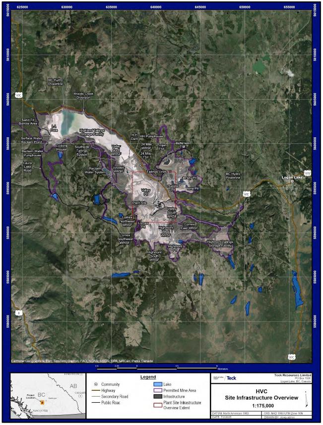
Figure 18-1: Current Infrastructure Location Plan, Site Overview
| October 2025 | Page 18- |
|
|
NI 43-101 Technical Report on Highland Valley Copper Operations British Columbia |

Figure 18-2: Current Infrastructure Location Plan, Mill Area Detail
| October 2025 | Page 18- |
|
|
NI 43-101 Technical Report on Highland Valley Copper Operations British Columbia |

Figure 18-3: Proposed Infrastructure Location Plan, Site Overview
| October 2025 | Page 18- |
|
|
NI 43-101 Technical Report on Highland Valley Copper Operations British Columbia |
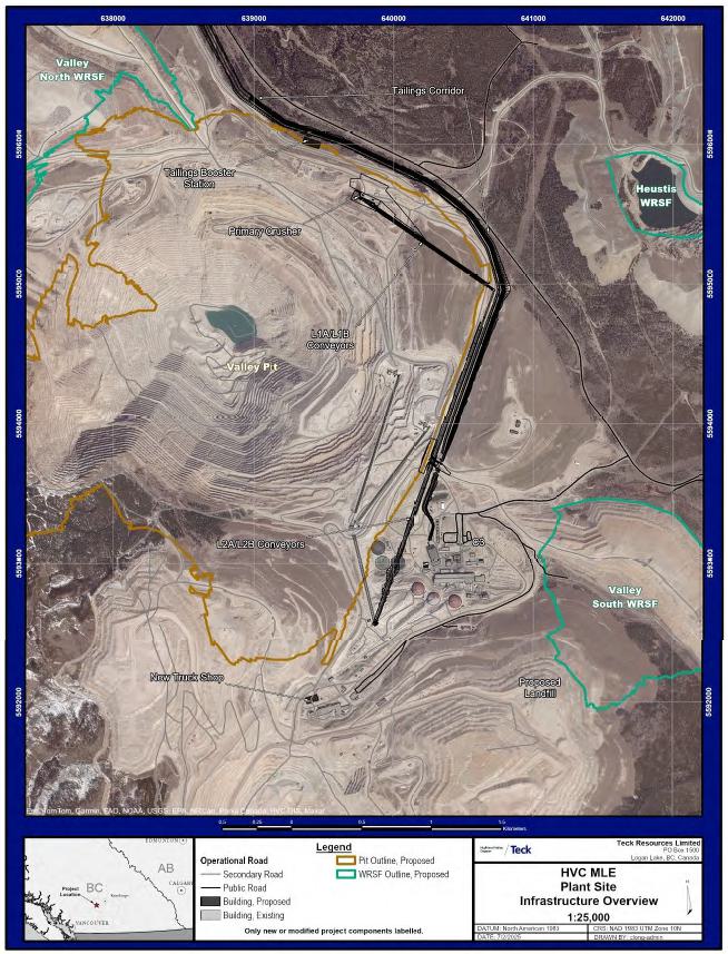
Figure 18-4: Proposed Infrastructure Location Plan, Mill Area Detail
| October 2025 | Page 18- |
|
|
NI 43-101 Technical Report on Highland Valley Copper Operations British Columbia |
| 18.6 | Tailings Storage Facilities |
| 18.6.1 | INTRODUCTION |
There are four major TSFs; three of which, Highmont, Bethlehem, and Trojan, are closed and reclaimed. The currently active primary TSF is the Highland TSF (refer to Figure 18-1).
Two auxiliary TSFs, the 7-Day Pond TSF and 24 Mile TSF, are also active. The 7-Day Pond TSF, located adjacent to the Highland mill, and 24 Mile TSF located downstream of the H-H dam, are classified as TSFs and receive minor amounts of tailings from the mill during upset conditions.
| 18.6.2 | HIGHLAND TSF |
The existing Highland TSF is located within a natural valley, is approximately 10 km long and 1.7 km wide and supported on either end of the valley by large, geotechnically engineered dams. The L-L dam is at the northwest end, and the H-H dam is at the southeast end. Tailings are deposited between the two dams. Key facility features are summarized in Table 18-1.
The tailings produced are primarily a fine- to medium-grained sand with some silt-sized particles and a low residual metals content. Tailings are transported through pipes by pumps and gravity to the Highland TSF where they are deposited for final storage. Approximately 150,000 t of tailings are discharged into the Highland TSF per day. Water is reclaimed from the facility for re-use in the Highland mill.
A free water pond is maintained at the western end of the TSF, separated from the core of the L-L dam by a wide compacted sand zone and a tailings beach.
The operational water volume stored in the Highland TSF typically ranges from about 10–25 Mm3 to meet process water needs. An additional inflow design flood storage capacity of 50 Mm3 is maintained above the operating pond level and below freeboard requirements at all times in the absence of a spillway.
During routine operations, water levels in the Highland TSF are managed to provide reclaim water for the mill throughout the year. Water levels are controlled via reclaim pumping from barges to the No. 2 booster station. At the No. 2 booster station, water is diverted to the cyclone house during cyclone operation and for construction water requirements. The remainder of the reclaim water is pumped to the raw water reservoir for use in the mill.
| 18.6.3 | LOM PLAN |
Upgrades are needed to accommodate approximately 1 billion tonnes of additional tailings that will be generated by the LOM plan at a rate of approximately 150,000 t/d. This will require raising the L-L dam to 1,310 m nominal elevation and the H-H dam to 1,326 m nominal elevation. The additions and modifications to the Highland TSF tailings infrastructure are required to increase the system capacity for the proposed flow rates and to accommodate the higher ultimate TSF tailings and water elevations resulting from the higher throughput and the LOM plan. Additional modifications and changes that will be required are summarized in Table 18-2.
| October 2025 | Page 18- |
|
|
NI 43-101 Technical Report on Highland Valley Copper Operations British Columbia |
Table 18-1: Current TSF and Associated Features
| Facility | Design |
| L-L dam |
Earthfill starter dam raised via the centerline method with a low permeability vertical glacial till core supported by a downstream zone of hydraulically placed, cycloned sand and an upstream cycloned sand zone/tailings beach. A drainage system at the base of the downstream shell of the dam comprises a drainage blanket and a series of finger drains. Active sediment ponds are located at the downstream toe of the L-L dam and are used to collect construction water and fine sediments from hydraulic sand placement on the downstream side of L-L dam. A pump system that transports water collected at the surface water reclaim pond back into the TSF |
| H-H dam | An earthfill starter dam raised via the centerline method supported by random fill and tailings beach on the upstream side and variable mine waste fill on the downstream side. Supported by WRSFs built immediately downstream. |
| 24 Mile TSF |
Downstream of the H-H dam and physically separate from the Highland TSF. Collects surface water runoff from adjacent creeks, as well as emergency tailings disposal from the H-H pumphouse during periods of tailings line maintenance and/or operational upsets. Formerly a natural lake that is now surrounded by WRSFs with no clearly defined dam structure. All seepage through the H-H dam mixes with other seepage within the WRSFs and flows south towards the Valley pit where it is intercepted by the pit dewatering wells and pumped to the mill for reuse. |
Table 18-2: TSF-Related Changes and Modifications Required In Support Of LOM Plan
| Area | Note |
| BC Hydro 138 kV transmission line and Highway 97C | Construction of the L-L dam and proximity of the pond may require relocation of several limited portions of the existing transmission line and highway (required in the period 2027–2034). |
| Laura Lake Road (public road) | Construction of the L-L dam necessitates relocation of about 2 km of the Laura Lake Road (2028). |
| South side tailings system and L-L cyclone house | South side 3 booster station will need to be replaced at higher elevation before 2038 to avoid inundation by tailings. The portion of the south side tailings system near the L-L cyclone house will need to be replaced to account for the expansion of the L-L dam (2028). The on-dam cyclones and piping at the L-L dam will continue to be raised coincident with dam construction. |
| Cyclone house modifications | Additional stage added to twinned underflow pumps (2028), pump system for drains and bypass (2029), addition of an emergency storage collection system for unplanned power outages (2029), upgrade to the underflow line flush capacity (2029), addition of cyclowash to primary cyclones (2029), and addition of a nuclear density meter to the primary cyclone feed (2029). |
| H-H dam pumphouse | Must be relocated outside of the LOM H-H dam footprint (2027). |
| Seepage and sediment management ponds | Sediment Pond 2, Seepage Pond 2, and the Surface Water Reclaim Pond are located within the LOM dam footprint and must be decommissioned and relocated in 2026/2027 to downstream of the LOM L-L dam ultimate footprint. |
| Powerlines and dam construction haul roads | Powerlines and haul roads located within the expanded footprints of both dams will need to be relocated. |
| Woods Creek diversion | The diversion pump station and portions of discharge piping will need to be relocated in 2026 to avoid inundation by the operating pond and expansion of the L-L dam buttresses. |
| Sulphate Adaptive Management Plan wells | Two of the existing wells are located within the L-L dam ultimate footprint and will require raising coincident with dam construction. |
| October 2025 | Page 18- |
|
|
NI 43-101 Technical Report on Highland Valley Copper Operations British Columbia |
The upgrades will be conducted in two phases:
| · | Phase 1: The initial phase for the tailings system involves the continued operation of the existing H-H pumphouse at its current location, while constructing a new tailings system relocated to align with the mine plan. Construction during this phase will include a new pipeline corridor, installation of a new tailings booster station, and sequential installation of new/relocated pipelines to support the transition from the existing tailings system to the new system with minimal impacts to ongoing operations; |
| · | Phase 2: Construction of the tailings booster sumps numbered 1 and 2 and a new mill diversion line surge pond. Temporary drainage systems initially flowing through a temporary trench towards the existing 24 Mile TSF will be re-worked to flow towards the new tailings booster sumps. The mill diversion line will also be truncated to feed the new mill diversion line surge pond once constructed. A new barge will be installed at the west end of the mill diversion line surge pond to reclaim water from the mill diversion line surge pond to the Highland TSF. |
During normal operating conditions, tailings will be pumped from the mill to the H-H dam pumphouse, where they will either be pumped directly into the TSF impoundment at the H-H dam east abutment spigots or pumped to the L-L dam via the existing south side tailings system. From the south side tailings system, tailings will either be discharged to the TSF impoundment at booster stations along the pipeline or pumped to the L-L dam cyclone house. At the cyclone house, underflow sand from the primary cyclones will be used for dam construction; the overflow will be used for beach construction.
Approximately 65% of the tailings will be spigotted into the Highland TSF at the east end of the H-H dam. The solids will settle in the TSF as the water flows towards the L-L dam. The remaining 35% of the tailings will be pumped to the L-L dam cyclone house for use in L-L dam construction and beach construction. A supernatant pond that will be situated close to the L-L dam will typically hold between 10–25 Mm3 of water. The water will be pumped back to the mill for use as process water. The dam crest will be maintained at a minimum height above pond level to accommodate tailings deposition, flood storage (~50 Mm3) and flood freeboard (~2 m); this represents the 120-hour probable maximum flood case.
The south side tailings system will convey tailings to the L-L dam where cyclones will separate whole tailings into overflow (primarily silt sizes) and underflow (primarily sand sizes). In the L-L cyclone house, which will be located at the L-L dam south abutment, primary cyclones will be typically operated year-round for L-L dam construction and beach development. The primary overflow will be discharged into the impoundment while primary underflow will either be used for upstream hydraulic cell construction or transported to the on-dam secondary cyclones, which will typically be operated for eight months of the year (1 April to 30 November). Secondary underflow will be used for downstream hydraulic cell construction while the secondary overflow will be discharged into the impoundment. Primary underflow and secondary overflow will be discharged to the beach through multiple discharge points spread out along the dam crest.
| October 2025 | Page 18- |
|
|
NI 43-101 Technical Report on Highland Valley Copper Operations British Columbia |
| 18.7 | Water Supply |
| 18.7.1 | CURRENT |
A site-wide operational water balance model is used for managing water for current mining operations. The mine uses approximately 109 Mm3 of water annually (approximately 82 Mm3 of which is reused). Water is recycled from the TSF pond via barge pumps to a booster pump station that pumps water to a reservoir approximately 150 m of elevation above the pond surface. The water then flows by gravity to the mill for use in processing. The process make-up water (approximately 27 Mm3 per annum) is currently supplied from a combination of surface runoff inflows, seepage inflows, and groundwater wells to replace losses primarily from evaporation on the TSF surface and entrainment in tailings.
Drinking water is obtained from wells close to the main plant site. It is pumped to a water treatment plant, where it is treated with a sodium hypochlorite process.
| 18.7.2 | LOM PLAN |
The site water supply strategy will not change through the LOM plan. The increase in throughput will require an increase in make-up water supply due to the additional water losses to tailings voids. It is expected that 272 m3/h or approximately 2.4 Mm3 of additional make-up water will be required over the current average LOM requirements. This water is planned to be sourced primarily from depressurization wells in the Valley pit.
Modifications to the Highland reclaim system infrastructure are required to increase the system capacity for LOM throughput and to accommodate the higher ultimate TSF tailings and water elevations in the LOM plan.
| 18.8 | Water Management |
| 18.8.1 | CURRENT |
Teck manages an inventory of local lakes and reservoirs that form an integral part of the non-contact (e.g., fresh water) and contact water (e.g., process water) management system on site. These lakes and reservoirs are contained by constructed dams and abutment structures ranging from approximately 3–22 m in height.
| 18.8.2 | LOM PLAN |
The site water management strategy will continue to rely on use of the Highland TSF. The increase in throughput requires an increase in make-up water supply due to the additional water losses to tailings voids. This water is planned to be sourced primarily from depressurization wells in the Valley pit. Teck has existing water licenses and infrastructure to meet this make-up water requirement. Opportunities exist for water storage in the pit bases that are not actively mined. This would allow water to be captured during wetter years for use during dry years.
| October 2025 | Page 18- |
|
|
NI 43-101 Technical Report on Highland Valley Copper Operations British Columbia |
The operational water volume stored on the Highland TSF typically ranges from about 10–25 Mm3 to meet process water needs. An additional flood storage capacity of 50 Mm3 is maintained on top of the operating pond at all times in the absence of a spillway.
Expansion of the L-L dam will encroach on the existing sediment, seepage, and surface water management infrastructure located at the toe of the valley buttress berm and replacement facilities will be required. Sediment pond 3 will be constructed outside of the L-L dam footprint.
New sediment and seepage collections ponds required include:
| · | West sediment pond, for management of sediment from the north dam, north buttress berm, valley buttress berm, and valley buttress berm extension construction; |
| · | New surface water reclamation pond, to be located downstream of the west sediment pond; |
| · | Sediment from the south dam area will continue to be managed in the south sediment pond; |
| · | Surface water diversions to the north along Highway 97C and the south at the Jim Black Lake weir, required to reduce the size of the flood management components of the ponds (i.e., freeboard, spillways, etc.). |
The Woods Creek diversion will require relocation in 2029 to continue operation throughout the LOM. No new diversions are required for the H-H dam. The 24 Mile TSF will be fully capped by WRSFs during the LOM and an alternative storage pond for overflow tailings from the tailings booster pumphouse is planned. For the period that the 24 Mile TSF remains uncapped, a pumping barge will continue to operate to manage the water level.
Pukaist Creek used to originate near the existing Valley pit and flow to the southwest within the Highland Valley. Construction of the Highland TSF blocked surface water flow in Pukaist Creek. After development of the Highland TSF, water continues to emerge in the creek channel at Pukaist Springs, approximately 3 km southwest of the L-L dam. Sulphate levels in the Pukaist Creek are associated with seepage from the Highland TSF.
A Sulphate Adaptive Management Plan began in 2013 with the intent to reduce sulphate concentrations and maintain base flows in Pukaist Creek. As part of this continued initiative, additional seepage interception wells are to be installed (four are currently installed) downstream of the L-L dam to intercept groundwater from the lower sand and gravel aquifer that is affected by the mine. The captured seepage will be pumped to the central collection pond downstream of L-L dam where it is recycled back to the impoundment. Teck is currently assessing other mitigation strategies that may be required to meet the objectives of the Sulphate Adaptive Management Plan for the LOM. An example would be the use of a freshwater infiltration scheme downstream of the interception wells to maintain base flows reduced by pumping from the interception wells. The Sulphate Adaptive Management Plan system will be operated until water quality indicates it is no longer necessary.
| October 2025 | Page 18- |
|
|
NI 43-101 Technical Report on Highland Valley Copper Operations British Columbia |
Relocations of crusher and conveyor equipment will impact the existing mill water pumphouse and 7-Day Pond TSF. The new water management system will consist of a new mill water pumphouse and two concrete sedimentation ponds located north of the existing flotation building; an existing natural low-lying area further north will serve as the new overflow pond. Each of the new concrete sedimentation ponds will be sized with nominal operating liquid/slurry capacity of 6,000 m3 and will be designed to accommodate up to 5,000 m3 of deposited solids, requiring periodic cleanout upon reaching their capacity limits. Concentrate thickener overflow, grinding building drainage, and flotation building emergency drainage water will be collected in the new sedimentation ponds. If both ponds are full, any overflow will be directed to the overflow pond. Under normal operating conditions, water from the overflow pond will be pumped back to the new mill water pumphouse. During excessive run-off events, if the ponds simultaneously reach their capacity, the overflow pond will ultimately overflow to the Valley pit.
| 18.9 | Camps and Accommodation |
The mine does not operate a camp or accommodation system; all employees are housed off-site. Due to the proximity of nearby communities and their relative population, all mine employees are expected to find suitable accommodation with personal access along Provincial Highway 97C to the mine site. Employees typically reside in Kamloops, Logan Lake, Merritt, Ashcroft, or smaller communities near the mine site.
| 18.10 | Power and Electrical |
Electrical power to the mine is currently provided by a single 138 kV transmission line. The transmission line runs from BC Hydro’s Nicola Substation to the Highland Valley Copper Operations with drops at three Teck-owned substations: Highmont substation adjacent to the mill, L-L dam substation at L-L dam, and Spatsum substation at the Spatsum pump house on the Thompson River.
The operations currently have a power supply agreement with BC Hydro, for 146 mega-volt amperes (MVA).
The LOM plan will require an increase in contract demand up to 180 MVA, with the largest additional draws being the SAG mill, C3 ball mill, tailings booster station, and mining equipment additions.
The LOM plan will require additional power-related infrastructure, consisting of:
| · | Addition of electrical equipment and electrical rooms associated with the SAG mill, C3 ball mill, flotation, tailings, and water reclaim areas; |
| · | On-site power distribution in new and existing areas including replacement, addition, and modification of existing 138 kV and 15 kV overland power lines; |
| · | Addition of a new 138 kV substation at Bethlehem. |
Teck is currently engaged with BC Hydro, the power provider, for the following upgrades to support the projected load growth:
| · | Reconductor transmission line 1L243 to increase its capacity and replace or reinforce structures where required; |
| October 2025 | Page 18- |
|
|
NI 43-101 Technical Report on Highland Valley Copper Operations British Columbia |
| · | Supply and install a 300 MVA 230/138 - 12.6 kV transformer at Nicola substation; |
| · | Re-routing the incoming 138 kV power supply to allow for WRSF expansion and re-routing of the 138 kV line at the Highland TSF; |
| · | Adding a tap to the existing 138 kV transmission line and metering point for the new Bethlehem substation. |
| 18.11 | Natural Gas |
Natural gas is provided by Fortis Energy Inc. and is conveyed via gas transmission lines that enter on the east side of the mine site and terminate at the Highland Valley Customer Station.
In support of the LOM plan, the utility corridor will need to be re-routed to allow for the extension of the Valley South WRSF.
| October 2025 | Page 18- |
|
|
NI 43-101 Technical Report on Highland Valley Copper Operations British Columbia |
19 MARKET STUDIES AND CONTRACTS
| 19.1 | Market Studies |
Teck’s market research team performs market studies for the metals and copper and molybdenum concentrates that Teck produces from the Highland Valley Operations. The following sub-sections summarize the demand and supply forecasts for copper and molybdenum from those market studies.
| 19.1.1 | COPPER DEMAND |
Copper consumption is divided into three main product groups: copper wire rod, copper products and copper alloy products. Copper wire rod (which includes, amongst other items, wires, and cables) is the primary use driving demand, accounting for 64% of total global consumption (including scrap). The remainder of global consumption is relatively evenly split between copper billet products and copper alloy products.
In general, copper is consumed in five broad sectors: construction, electrical network infrastructure, industrial machinery and equipment, transportation equipment, and consumer and general products. Of these, electrical networks is the largest copper-consuming sector, accounting for 29% of total copper consumption.
Traditional end-use consumption represented 87% of copper demand in 2024. Growth of traditional demand is driven from urbanization and expansion of the middle class. Copper consumption is forecast to grow by approximately 3% over the next five years. China, India, combined with South East Asia will account for 45% of expected growth out to 2030. China’s demand forecast is set to benefit from growth in consumer durables, large-scale domestic equipment, and infrastructure investment, more than offsetting a recent decline in residential construction. Increasing trade tensions, especially from the US, and further decline of the real estate sector could negatively impact short-term copper consumption. The demand from the rest of Asia is expected to benefit from industrial migration, as companies diversifying outside China, US demand could also account for 13% of demand growth out to 2030 in the current push towards onshoring continues.
New energy transition is still forecast to be the largest contributor to future copper demand growth rates. Despite softening demand in the near-term, electric vehicles remain a large driver of copper demand growth by 2050. Power grids are the second largest contributor to actual growth and are expected to add about 10 Mt to copper consumption by 2050. However, digitalization (the transformation of business processes and models using digital technologies), grid efficiency, and demand flexibility are expected to reduce sector growth beyond 2030. Chinese green energy demand is predicted to continue to outpace the rest of the world in the near-term, until the country reaches technology saturation by end of the 2030s. By the mid-2030s, Southeast Asia demand is forecast to surge as that area becomes the fastest-growing region in the world.
| 19.1.2 | COPPER SUPPLY |
Copper mine production remains challenged with mine disruptions expected to come in above average in the short to medium term. Mine supply growth is centred on a small number of large mines, with just 11 mines accounting for over 60% of the projected growth out to 2028 peak production. The copper concentrate market is forecast to remain in deficit moving forward unless significant new investment in primary copper production is made. Mine production grew by 7 Mt over the last 20 years, and this will need to be repeated in the next 10 years to meet growing demand.
| October 2025 | Page 19- |
|
|
NI 43-101 Technical Report on Highland Valley Copper Operations British Columbia |
Declining grades, escalating costs, slow permitting, and underinvestment continue to negatively impact new mine production, prolonging the concentrate market deficit. Copper ore grades have been declining for years, with the trend not expected to reverse any time soon. Lower grades require higher quantities or ores to be processed to maintain production levels, increasing costs.
Copper scrap is part of the long-term solution, supplementing tight concentrate marketing. The demand for scrap will escalate over the next decade with end users increasingly requiring higher recycled content. Copper scrap makes up 35% of total copper demand and is expected to rise to 40% by 2035.
Trade flows are likely to change due to growth in secondary projects in North America, Europe, India, South Korea, and Japan. Chinese smelters’ dependency on scrap will increase to make up for insufficient concentrate feed, however, export restrictions by the United States and/or Europe could impede this growth forcing buyers into the primary market. Chinese scrap imports were up 13% in 2024, but were down 1% in the first five months of 2025. Figure 19-1 demonstrates the expected growing gap between mine supply and copper demand.
| 19.1.3 | COPPER CONCENTRATE MARKETABILITY |
Key considerations regarding the Highland Valley copper concentrate marketability include:
| · | The copper concentrate is a well-established copper concentrate in the market with long-term, reliable Asian smelter customers; |
| · | The annual concentrate production will continue to be small compared to the global concentrate market, and no major challenges are expected in maintaining reliable and sustainable sales options for the LOM; |
| · | The copper concentrate is not expected to have any notable levels of deleterious elements such as arsenic, antinomy, mercury, zinc, and lead. This gives the concentrate a competitive edge in marketability. |
The copper grade in concentrate will average approximately 35% over the LOM, which classifies it as a high-grade product.
| October 2025 | Page 19- |
|
|
NI 43-101 Technical Report on Highland Valley Copper Operations British Columbia |

Note: Figure prepared by Teck, 2025
Figure 19-1: Copper Mine Production and Demand (kt)
| 19.1.4 | MOLYBDENUM DEMAND |
Molybdenum is used in an extensive number of applications; however, global molybdenum consumption can be summarized into seven larger first uses. Globally, molybdenum is used primarily as an alloy in several types of steel production; it is also used as a catalyst and lubricant in several chemical applications. Steel and alloy demand account for over 88% of molybdenum demand; this is driven by molybdenum’s ability to withstand high temperatures without expanding or softening. For these reasons, it is used extensively in high strength or hardened steels, cast irons, or tool steels. Molybdenum is also highly valued for its corrosion resistance and weldability and is used extensively in 300-series stainless steels for its corrosion resistance.
Steel demand tends to follow the global economy and industrial production, but with a different time lag in its various sub sectors. More than 90% of steel produced in the world is ordinary carbon steel, which uses very little additional molybdenum. This carbon steel still accounts for 8% of total molybdenum use by its sheer volume. Most carbon steels that do contain molybdenum only require small quantities (0.08% to 0.15% of Mo addition). Of more importance to the molybdenum market are the remaining 8–10% of steel production known as specialty steels. Depending on the type and application, these steels can contain from 0.25–9.5% Mo. Figure 19-2 provides the molybdenum demand growth forecast by industry.
| October 2025 | Page 19- |
|
|
NI 43-101 Technical Report on Highland Valley Copper Operations British Columbia |

Note: Figure prepared by Teck, 2025.
Figure 19-2: Global Demand Growth of Molybdenum by Industry
| 19.1.5 | MOLYBDENUM SUPPLY |
Molybdenum is mined globally as the primary metal being extracted or it is present in large copper ore deposits in sufficient grade and quantity that it is deemed economic to recover. Currently, over half (58%) of the molybdenum globally is a by-product of copper mining. In times of low prices, this percentage has increased to as high as 70%. In the 1980s and again in 2017, mine production was strongly in favour of by-product molybdenum mines. This is important, because decisions to mine are driven by copper market prices and conditions rather than molybdenum prices and market trends.
Higher molybdenum prices tend to bring high-cost primary mine production to the market, and in the past, this has changed the amount of molybdenum that China will consume/import or export to global markets. As China moves further down the value chain into higher-grade specialty steels, the Chinese willingness or ability to export excess molybdenum could be restricted.
| 19.1.6 | MOLYBDENUM CONCENTRATE MARKETABILITY |
Teck currently sells its molybdenum concentrate production in the custom roasting market as molybdenum concentrates. The market for custom molybdenum concentrates outside of China is split almost equally between three major firms, with a couple of smaller players. There are no significant changes forecast to the molybdenum concentrate quality and the sales of future molybdenum concentrate from the Highland Valley Operations are expected to continue to be made into the custom-roasting market.
| October 2025 | Page 19- |
|
|
NI 43-101 Technical Report on Highland Valley Copper Operations British Columbia |
| 19.2 | Commodity Price Projections |
Teck has implemented a standardized approach for commodity price and exchange rates to be used in estimating Mineral Resources and Mineral Reserves, and in the cashflow analyses that support the Mineral Reserves.
Teck assessed a combination of several components when considering pricing forecasts for copper and molybdenum including consensus survey long-term prices, investment dealers’ long-term prices, the average 10-year real price, and long-term commodity forecasters’ prices.
Similar to the commodity prices, the exchange rate is assessed using consensus survey data, the average 10-year rates, purchasing power parity bases, and investment dealers’ long-term rates.
Commodity price and other economic input assumptions are annually reviewed and approved by the Technical Committee of the Teck Board of Directors.
The forecasts are included in Table 19-1.
| 19.3 | Contracts |
Teck will retain ownership of the copper concentrates until the concentrates are sold to customers. Teck’s Marketing Team will function as the marketing agent for products produced at Highland Valley Copper and will be responsible for managing all aspects of the sale of the copper and molybdenum concentrate including all associated logistics.
Teck currently has entered into spot, medium- and long-term contracts with international shipping companies to deliver Highland Valley Copper concentrates sold under sales agreements with customers. The future contract approach will continue to have a set of spot, medium- and long-term contracts with a diverse set of customers, all of which will be managed by Teck.
Bulk copper concentrate is trucked to the Canadian National Ashcroft rail transload facility. Concentrates are then transported by rail from the transload facility to the Pembina Vancouver wharves. Contracts are currently in place for trucking, transload, port and rail services for the copper and molybdenum concentrates, and are expected to be renewed within industry norms.
Teck has contracts in place with third-parties that provide services, supplies, and construction services to the site. These contracts include mining services and supplies required for the operation such as explosives, reagents, and contract maintenance activities. Contracts are managed by Highland Valley Copper’s supply chain department and are expected to be renewed within industry norms for the LOM.
| 19.4 | QP Comment on Item 19 “Market Studies and Contracts” |
All concentrate sales from Highland Valley Copper Operations are to be managed by Teck’s marketing and logistics team. Concentrate sales will continue to use spot, medium- and long-term contracts as is done today. In the QP’s opinion, the terms of the copper and molybdenum concentrate sales agreements are within the reasonable range of market value treatments. Teck does not hedge its production prices from the Highland Valley Copper Operations.
| October 2025 | Page 19- |
|
|
NI 43-101 Technical Report on Highland Valley Copper Operations British Columbia |
Table 19-1: Metal Price and Exchange Rate Forecasts
| Commodity/Exchange Rate | Units | Value |
| Copper | US$/lb | 3.80 |
| Molybdenum | US$/lb | 15.20 |
| US/CAD Exchange rate | US$/CAD$ | 1.31 |
The price assumptions in Table 19-1 have a reasonable basis and can be used in Mineral Resource and Mineral Reserve estimation and in the cashflow analysis that supports the Mineral Reserves.
Contracts other than concentrate sales contracts are typical of such third-party contracts in Canada that the QP is familiar with.
| October 2025 | Page 19- |
|
|
NI 43-101 Technical Report on Highland Valley Copper Operations British Columbia |
20 ENVIRONMENTAL STUDIES, PERMITTING, AND SOCIAL OR COMMUNITY IMPACT
| 20.1 | Introduction |
The operations currently operate under provincial Mines Act Permit M-11 (formerly Reclamation Permit M-11), first issued on 20 January, 1970. The permit has been amended over time to reflect the mine’s development and amalgamated separate provincial Mines Act Permits originally granted for the Bethlehem and Highmont operations.
| 20.2 | Baseline and Supporting Studies |
Numerous studies have been completed in support of permit applications. The most recent set of studies were completed in support of the application for an Environmental Assessment Certificate issued 17 June 2025, approving the LOM plan envisaged in this Report. The amended M-11 permit was issued on 18 June, 2025.
The following studies were included as part of the application:
| · | Air quality; |
| · | Noise; |
| · | Hydrogeology; |
| · | Surficial hydrology; |
| · | Water quality; |
| · | Fish and aquatic resources; |
| · | Vegetation and ecosystems; |
| · | Wildlife and wildlife habitat; |
| · | Socio-economic; |
| · | Infrastructure and services; |
| · | Human health effects; |
| · | Heritage Resources effects; |
| · | Culture existing conditions and effects; |
| · | Land and resource use; |
| · | Assessment of Indigenous interests. |
In each case, the study identified and evaluated the potential positive and negative direct and indirect effects of the LOM plan on the effects of each impact within a local and regional context and subsequent effects management, residual effects, and cumulative effects.
| October 2025 | Page 20- |
|
|
NI 43-101 Technical Report on Highland Valley Copper Operations British Columbia |
| 20.3 | Environmental Monitoring |
Teck has established environmental monitoring programs for the operations, which include comprehensive monitoring of the mine site, discharge locations, and the receiving environment. The existing environmental monitoring programs are intended to enable ongoing evaluation of environmental management performance and receiving environment conditions. Monitoring activities are coordinated and tracked by the Environment Department.
Monitoring programs that are in place include:
| · | Surface water quantity and quality monitoring; |
| · | Groundwater quantity and quality monitoring; |
| · | Aquatic effects monitoring; |
| · | Effluent discharge monitoring of landfill leachate; |
| · | Meteorological monitoring; |
| · | Air quality (dust) monitoring; |
| · | Light scatter monitoring; |
| · | Metals leaching and acid rock drainage monitoring of waste materials; |
| · | Wildlife monitoring; |
| · | Vegetation monitoring; |
| · | Invasive plants surveys; |
| · | Erosion and sediment control monitoring; |
| · | Reclamation and post-closure monitoring. |
Long-term monitoring stations have been established for environmental monitoring programs and will be maintained throughout the LOM to facilitate long-term trend analysis. Monitoring of effluent discharge locations is conducted concurrently with receiving environment stations to evaluate the relationship between effluent discharge and receiving environment water quality. Monitoring frequency has been established to account for seasonal variability which may influence water quality and constituent loading in the receiving environment. As part of its adaptive management strategy, Teck evaluates environmental monitoring programs on a routine basis to assess the effectiveness of monitoring locations and methodology. These programs may be expanded in future to include additional monitoring locations or increased monitoring frequencies if monitoring results indicate environmental effects may be occurring, to inform adaptive management, or based on feedback from Indigenous Governments and Organizations.
Monitoring programs are spatially comprehensive, and established sampling and QA/QC methods will continue to be used throughout the LOM.
| October 2025 | Page 20- |
|
|
NI 43-101 Technical Report on Highland Valley Copper Operations British Columbia |
| 20.4 | Closure |
| 20.4.1 | CLOSURE PLAN |
The Ministry of Mining and Critical Minerals must be provided with a reclamation and closure plan at the start of operations. The plan must be updated and provided to the Chief Inspector following the initial submission at least every five years.
The plan must include information related to the mine, reclamation and closure planning, including but not limited to a description of the status of the mine plan and reclamation obligations, a detailed mine plan for the following five years and a conceptual mine plan until the end of mine life, the life of mine closure plan including closure objectives, closure and maintenance activities, metrics of success and implementation schedule, and a detailed summary of outstanding site-wide liabilities and associated costs for the mine plan and reclamation plan.
Highland Valley Copper also maintains an End Land Use Plan, which establishes end land use objectives, post-closure capability metrics and site-specific reclamation prescriptions to inform the reclamation and closure planning. The End Land Use Plan must be updated every 10 years and incorporated into reclamation and closure planning.
A comprehensive closure plan was submitted as part of the Environmental Assessment Certificate application. The next update of the End Land Use Plan and the regulatory reclamation and closure plan must be completed and submitted in December 2026.
| 20.4.2 | CLOSURE COSTS |
The reclamation liability cost estimate for the Highland Valley Copper Operations follows the Ministry of Mining and Critical Minerals guidance for the development of reclamation liability cost estimates, and includes the following components:
| · | Infrastructure removal; |
| · | Site remediation; |
| · | Conventional reclamation; |
| · | Water quality mitigations; |
| · | Site staffing; |
| · | Site maintenance; |
| · | Site monitoring and reporting. |
Inflation, discount rates, contingency costs, and other indirect costs such as engineering and project management contained in the reclamation liability cost estimate are also aligned with the Ministry of Mining and Critical Minerals Guidance.
The reclamation liability cost estimate was updated in 2024 as part of the Environmental Assessment Certificate application, resulting in a total estimated liability of $959 M. The reclamation liability cost estimate is updated and submitted annually as part of the site annual regulatory reporting, every five years in alignment with the submission of the regulatory reclamation and closure plan, and with every substantial Mines Act M-11 permit amendment application.
| October 2025 | Page 20- |
|
|
NI 43-101 Technical Report on Highland Valley Copper Operations British Columbia |
Teck currently has approximately $351 M of bonding in place with the Ministry of Finance, and will be required to post an additional $368 M by 30 September 2025 to ensure that the closure cost estimate is fully bonded.
| 20.5 | Permitting |
The operations received Mines Act Permit M-11 in 1970 and still operate under that permit, as amended. The most recent amended M-11 permit was issued on 18 June, 2025. The operations has additional permits, licences and authorizations required to construct, operate, and close the operations. Table 20-1 describes the existing authorizations. Table 20-2 summarizes the key permits that are expected to require renewal during the LOM plan.
| 20.6 | Considerations of Social and Community Impacts |
Teck understands that maintaining strong relationships with local Indigenous Governments and Organizations and other communities of interest is essential to facilitating responsible mining and generating economic benefits, advancing reconciliation efforts, and improving community well-being. Social management at Teck is guided by Teck’s Social Performance Standard.
| 20.6.1 | SOCIAL PERFORMANCE STANDARD |
Teck has implemented a social performance standard, which replaced the previous Social Management and Responsibility at Teck Framework. The standard defines the expectations and processes for the effective management of Teck’s social performance and relationships with Communities of Interest through all stages of the mining life cycle. It reflects and integrates relevant compliance obligations and evolving performance expectations informed by voluntary commitments and industry memberships, investors, and society. The Social Performance Standard includes procedures and guidelines that include, but are not limited to, the topics of community engagement, community investment, Indigenous Agreements, human rights, and social management planning.
In accordance with the Social Performance Standard, an annual review and mapping of communities of interest and social risks informs the development of a Social Management Plan that guides annual site-level strategies and plans for community engagement and social impact management.
| October 2025 | Page 20- |
|
|
NI 43-101 Technical Report on Highland Valley Copper Operations British Columbia |
Table 20-1: Key Permits
| Name of Authorization | Statute and Authorizing Agency |
Description / Need for Authorization |
| M-11 Mines Act Permit Approving Mine Plan and Reclamation Program | Mines Act, MCM | Permit for current mining operations. |
| PA-1557 Air Discharge Permit | Environmental Management Act, ENV | Permit for current operations air discharges. |
| PE-376 Effluent Discharge Permit | Environmental Management Act, ENV | Permit for current operations effluent discharges. |
| PR-2460 Waste (Refuse) Discharge Permit | Environmental Management Act, ENV | Permit for current operations landfill. |
| BC-10055 Explosives Storage and Use Permit | Mines Act, MCM | Permit for current operations explosives storage and use. |
| F1-075223/E Division 1 Factory Licence | Explosives Act, Natural Resources Canada | Licence for current operations. |
Notes: MCM = BC Ministry of Mining and Critical Minerals; ENV = BC Ministry of Environment and Parks. Water licences to support operations were discussed in Section 4.5.
| October 2025 | Page 20- |
|
|
NI 43-101 Technical Report on Highland Valley Copper Operations British Columbia |
Table 20-2: Additional Key Permits and Authorizations for LOM Plan
| Name of Authorization |
Statute and Authorizing Agency |
Description / Need for Authorization | Approx. Timing for Regulatory Decision |
| M-11 Permit Approving Mine Plan and Reclamation Program | Mines Act, MCM | An amendment will be required for facilities included in LOM plan, including geotechnical design updates for the Highmont and Valley Pits. | 2028 and later |
| Amendment to Waste Discharge Permit – Air (PA1557) | Environmental Management Act, ENV | An amendment to include new discharge locations and authorize associated pollution control measures and mitigations for discharge of airborne contaminants into the environment. | 2027 or later |
| Annual Renewal of Explosives Factory Licence | Explosives Act, Natural Resources Canada | Explosive Licence required for factories and magazines. | 2027 or later |
| Amendment to Explosives Storage and Use Permit (BC-10055) | Mines Act, MCM | Teck will seek extension of timelines for storage and use of explosives. | 2028 |
| Permits for works on rights of way (section 62) | Transportation Act, MOTT | Includes utilities, exploratory surveys, monitoring wells, etc. | 2028 or later |
| Statutory Right of Way | Land Act, MoF | Establish Highway 97C right of way for new alignment (assumes all land is Crown land). | 2028 or later |
| Access permits | Transportation Act and Industrial Roads Act, MOTT |
Highway access permits include: · access over unconstructed rights of way; · commercial access; · resource and industrial road access; · access to a controlled access highway. Highway access permits are required for all accesses. Controlled Access Highways (e.g., Highway 97C) carry requirements for access, with a preference for an alternate access to a development. |
2028 or later |
| Section 9: Water Licence. New Licences or Amendment to Existing Licences | Water Sustainability Act, MoF | Any ongoing water use or diversion, or the construction of a regulated dam, requires a water licence (for example, long-term water use for construction or operations). Application for authorization will include a list of diversions and associated effects specific to the water body. | 2028 or later |
| Section 10 authorization – Use approvals | Water Sustainability Act, MoF | Short-term (up to 24 months) diversion or use of water (surface water or groundwater) for construction purposes will require authorization. Short-term use approvals also allow for the construction of most works related to the diversion and use of water. | 2028 or later |
| October 2025 | Page 20- |
|
|
NI 43-101 Technical Report on Highland Valley Copper Operations British Columbia |
| Name of Authorization |
Statute and Authorizing Agency |
Description / Need for Authorization | Approx. Timing for Regulatory Decision |
| Section 11 authorization – Changes in and about a stream | Water Sustainability Act, MoF | Life of mine construction activities that affect a stream or surrounding riparian area (i.e., below the natural boundary) will require approval. | 2028 or later |
| Authorization(s) under section 35 for HADD of fish habitat | Fisheries Act, DFO | Authorization(s) will be required for changes in fish habitat associated with the Woods Creek diversion | 2028 or later |
| MDMER Schedule 2 Amendment | Fisheries Act, ECCC | Highland TSF extension will require registration under MDMER. | 2027 or later |
| Cultural Heritage inspection, investigation, and site alteration permits | Heritage Conservation Act, MoF, Archaeology Branch | A permit is required if any archaeological sites may be affected by construction activities related to the LOM plan. The permits must be acquired if an area or site needs to be evaluated for archaeological potential, studied for heritage properties, or altered. All permits must be held by a Registered Archaeologist. | If and as required |
Note: DFO = Fisheries and Oceans Canada; ECCC = Environment and Climate Change Canada; ENV = BC Ministry of Environment and Parks; HADD = harmful alterations, disruption, or destruction; MDMER = Metal and Diamond Mining Effluent Regulations; MoF = BC Ministry of Forests; MOTT = BC Ministry of Transportation and Transit; TSF = tailings storage facility.
| 20.6.2 | INDIGENOUS COMMUNITIES |
Teck recognizes that respecting the rights, cultures, interests, and aspirations of Indigenous people is fundamental to the operation and to meeting the company’s commitment to responsible resource development. As such, Teck, via its subsidiary Highland Valley Copper, has established formal agreements with Nlaka’pamux Governments and Organizations as well as the Stk'emlupsemc te Secwepemc Nation. The agreements are intended to provide the foundation for long-term, mutually beneficial relationships and a framework for communication, collaboration, and cooperation in areas such as employment, contracting and procurement, environmental management, regulatory matters, cultural heritage management, closure, and economic benefits.
In accordance with these agreements, Highland Valley Copper staff and representatives from Indigenous Governments and Organizations align on annual priorities and objectives in areas respective to each agreement and hold regular agreement implementation committee and technical working group meetings. A condition of the M-11 Mines Act permit includes the establishment and maintenance of a Nlaka’pamux Implementation Board that includes Nlaka’pamux representatives to provide advice on environmental management, monitoring, reclamation, and closure activities of the Highland Valley Copper operations.
| October 2025 | Page 20- |
|
|
NI 43-101 Technical Report on Highland Valley Copper Operations British Columbia |
| 20.6.3 | COMMUNITY INVESTMENT PROGRAM |
Teck’s Community Investment Program provides opportunities for investments in organizations and initiatives that create shared value, support sustainable development, and focus on shared strategic outcomes that help advance the achievement of the United Nations’ Sustainable Development Goals.
The Community Investment Program focuses on:
| · | Nature and climate: programs aligned with environmentally sustainable practices primarily aimed at mitigating climate change, and protecting and increasing biodiversity; |
| · | Community wellness: programs and initiatives that improve the health, well-being, and overall quality of life in communities where Teck operates; |
| · | Indigenous: Indigenous led or requested programs or initiatives to support reconciliation; |
| · | Education and equity: programs and initiatives designed to address educational disparities and promote fairness and inclusivity within communities. |
| October 2025 | Page 20- |
|
|
NI 43-101 Technical Report on Highland Valley Copper Operations British Columbia |
21 CAPITAL AND OPERATING COSTS
| 21.1 | Capital Cost Estimates |
Capital cost forecasts are based on a 21-year mine life, from 2025–2046, with the first and last years being partial years. The estimated capital expenditures reflect funds to support operations, including funding for new and expanded facilities, infrastructure, equipment additions and replacements, and in-pit drilling.
Key elements for growth capital, which covers the initial expansion phase from 2025–2027 include:
| · | Replacement of the D-line autogenous mill with a semi-autogenous mill; |
| · | Construction of the C3 tertiary stage ball mill; |
| · | Modifications to the mill flotation and tailings systems; |
| · | Mine equipment, including additional and replacement equipment for the mine fleet; |
| · | Construction of a new truck maintenance shop; |
| · | In-pit drilling. |
Key elements for sustaining capital estimates include:
| · | Relocation of the semi-mobile Valley in-pit crushers; |
| · | Relocation of the tailings delivery system, including new pump houses; |
| · | Relocation of critical infrastructure such as power lines, natural gas lines and roads; |
| · | Mine equipment, including additional and replacement equipment for the mine fleet. |
Capital cost estimates for the LOM are summarized in Table 21-1 and total approximately $4,275 M.
| 21.2 | Operating Cost Estimates |
Operating cost forecasts are based on a 21-year mine life, from 2025–2046, with the first and last years being partial years. Operating costs include the mine, mill and administration costs related to site production and do not include off-site costs such as marketing and freight.
Cost estimates are based on actual site operating cost history and budgetary estimates.
Key cost inputs include:
| · | Mining operations including drilling, blasting, loading, and hauling (all include labour, maintenance, and consumables), supervision and mine technical services; |
| · | Milling operations including labour, energy, consumables, maintenance, water, tailings, supervision and mill technical services; |
| · | Administration including site finance, human resources (including training), environment, community relations, health and safety, business improvement, supply chain management, and digital systems. |
| October 2025 | Page 21- |
|
|
NI 43-101 Technical Report on Highland Valley Copper Operations British Columbia |
Table 21-1: Capital Cost Estimate Summary Table (C$M, nominal terms)
| (C$M) | Total | 2025 | 2026 | 2027 | 2028 | 2029 | 2030 | 2031 | 2032 | 2033 | 2034 | 2035 |
| Growth | 2,229 | 369 | 916 | 813 | 129 | 3 | — | — | — | — | — | — |
| Sustaining | 2,046 | 69 | 116 | 163 | 227 | 290 | 347 | 162 | 72 | 54 | 48 | 64 |
| Total | 4,275 | 438 | 1,031 | 976 | 356 | 292 | 347 | 162 | 72 | 54 | 48 | 64 |
| (C$M) | 2036 | 2037 | 2038 | 2039 | 2040 | 2041 | 2042 | 2043 | 2044 | 2045 | 2046 |
| Growth | — | — | — | — | — | — | — | — | — | — | — |
| Sustaining | 67 | 64 | 60 | 58 | 40 | 36 | 36 | 36 | 24 | 12 | — |
| Total | 67 | 64 | 60 | 58 | 40 | 36 | 36 | 36 | 24 | 12 | — |
Note: all numbers have been rounded.
Operating cost estimates for the LOM are summarized in Table 21-2 and total approximately $19,062 M. The unit operating cost estimate for the LOM averages $17.32/t milled, with details provided in Table 21-3.
| 21.3 | Closure Costs |
Closure costs are discussed in Section 20.4.
| October 2025 | Page 21- |
|
|
NI 43-101 Technical Report on Highland Valley Copper Operations British Columbia |
Table 21-2: Operating Cost Estimate Summary Table (C$M, nominal terms)
| (C$M) | Total | 2025 | 2026 | 2027 | 2028 | 2029 | 2030 | 2031 | 2032 | 2033 | 2034 | 2035 | 2036 |
| Mine | 9,925 | 224 | 487 | 571 | 540 | 577 | 610 | 605 | 622 | 597 | 598 | 568 | 599 |
| Mill | 7,528 | 200 | 368 | 376 | 378 | 366 | 376 | 376 | 377 | 376 | 376 | 372 | 369 |
| Admin | 1,609 | 43 | 112 | 103 | 89 | 89 | 83 | 83 | 84 | 83 | 83 | 82 | 83 |
| Total | 19,062 | 467 | 968 | 1,050 | 1,007 | 1,032 | 1,069 | 1,064 | 1,082 | 1,056 | 1,057 | 1,022 | 1,050 |
| (C$M) | 2037 | 2038 | 2039 | 2040 | 2041 | 2042 | 2043 | 2044 | 2045 | 2046 |
| Mine | 587 | 572 | 332 | 270 | 276 | 311 | 328 | 316 | 284 | 53 |
| Mill | 369 | 372 | 363 | 363 | 365 | 344 | 332 | 332 | 321 | 56 |
| Admin | 82 | 82 | 79 | 60 | 60 | 60 | 55 | 52 | 51 | 9 |
| Total | 1,037 | 1,027 | 775 | 694 | 701 | 715 | 715 | 700 | 656 | 118 |
Note: all numbers have been rounded.
Table 21-3: Unit Operating Cost Estimate Summary Table (C$/t, nominal terms)
| Total | 2025 | 2026 | 2027 | 2028 | 2029 | 2030 | 2031 | 2032 | 2033 | 2034 | 2035 | 2036 | |
| Mine ($/t mined) | 3.45 | 3.89 | 3.66 | 3.06 | 2.59 | 2.65 | 2.75 | 2.73 | 2.94 | 3.19 | 3.46 | 3.48 | 3.58 |
| Mill ($/t milled) | 6.84 | 7.34 | 7.59 | 6.57 | 6.75 | 6.77 | 7.05 | 7.73 | 7.79 | 7.90 | 7.16 | 5.97 | 6.32 |
| Admin ($/t milled) | 1.46 | 1.56 | 2.31 | 1.80 | 1.59 | 1.65 | 1.56 | 1.72 | 1.73 | 1.74 | 1.57 | 1.32 | 1.41 |
| Total ($/t milled) | 17.32 | 17.12 | 19.94 | 18.37 | 17.96 | 19.07 | 20.04 | 21.89 | 22.37 | 22.21 | 20.09 | 16.39 | 17.97 |
| 2037 | 2038 | 2039 | 2040 | 2041 | 2042 | 2043 | 2044 | 2045 | 2046 | |
| Mine ($/t mined) | 3.92 | 3.80 | 4.60 | 4.76 | 4.93 | 4.91 | 5.22 | 5.67 | 5.39 | 5.45 |
| Mill ($/t milled) | 6.75 | 6.63 | 6.57 | 6.82 | 6.98 | 6.63 | 6.52 | 6.50 | 6.26 | 5.82 |
| Admin ($/t milled) | 1.50 | 1.46 | 1.43 | 1.13 | 1.15 | 1.16 | 1.09 | 1.02 | 1.00 | 0.99 |
| Total ($/t milled) | 19.00 | 18.27 | 14.00 | 13.01 | 13.42 | 13.78 | 14.05 | 13.70 | 12.81 | 12.32 |
Note: all numbers have been rounded.
| October 2025 | Page 21- |
|
|
NI 43-101 Technical Report on Highland Valley Copper Operations British Columbia |
22 ECONOMIC ANALYSIS
Teck is relying on the exemption whereby producing issuers may exclude the information required under Item 22 for technical reports on properties currently in production and where no material production expansion is planned.
The Mineral Reserve declaration is supported by overall site positive cash flows and net present value assessments.
| October 2025 | Page 22- |
|
|
NI 43-101 Technical Report on Highland Valley Copper Operations British Columbia |
23 ADJACENT PROPERTIES
This Section is not relevant to this Report.
| October 2025 | Page 23- |
|
|
NI 43-101 Technical Report on Highland Valley Copper Operations British Columbia |
24 OTHER RELEVANT DATA AND INFORMATION
This Section is not relevant to this Report.
| October 2025 | Page 24- |
|
|
NI 43-101 Technical Report on Highland Valley Copper Operations British Columbia |
25 INTERPRETATION AND CONCLUSIONS
| 25.1 | Introduction |
The QPs note the following interpretations and conclusions, based on the review of data and information available for this Report.
| 25.2 | Ownership |
The operations are wholly-owned by Teck Resources Limited. Teck uses a subsidiary company, Teck Highland Valley Copper Partnership, as the operating entity.
| 25.3 | Mineral Tenure, Surface Rights, Water Rights, Royalties and Agreements |
Information obtained from Teck experts supports that the mineral tenure held is valid, and the mineral tenures held are sufficient to support a declaration of Mineral Resources and Mineral Reserves.
Surface rights are sufficient to allow current mining operations. Additional land acquisition may be required to support the LOM plan.
Water rights are granted, and sufficient to support mining operations. Water licences are renewed as necessary per the BC Water Sustainability Act.
The Project is not subject to any royalties. Nor is it subject to any other back-in rights payments, agreements, or encumbrances.
To the extent known, there are no other significant factors and risks that may affect access, title, or the right or ability to perform work on the Project that have not been discussed in this Report.
| 25.4 | Geology and Mineralization |
The deposits are considered to be classic examples of porphyry copper–molybdenum deposits.
The geological understanding of the settings, lithologies, and structural and alteration controls on mineralization in the different zones is sufficient to support estimation of Mineral Resources and Mineral Reserves. The geological knowledge of the area is also considered sufficiently acceptable to reliably inform mine planning.
The mineralization style and setting are well understood and can support declaration of Mineral Resources and Mineral Reserves.
The lateral extents of the Valley deposit are generally well defined, but the deposit remains open locally at depth.
Mineralization at the Lornex deposit remains open to the south, southeast and at depth. Beneath the Lornex deposit there is considerable potential to extend mineralization as the high-clay and sericite alteration as well as the higher pyrite content compared to the Valley deposit suggests this is a higher-level expression of the system.
| October 2025 | Page 25- |
|
|
NI 43-101 Technical Report on Highland Valley Copper Operations British Columbia |
The lateral extents of the Highmont deposit generally well defined except to the east. Mineralization also locally remains open at depth within the Highmont deposit. As the Highmont deposit contain multiple mineralized porphyry centres it is possible for further such centres to be discovered in the area.
The Bethlehem deposit is generally well constrained, with limited depth potential. Jersey North is an occurrence located about 400 m to the north of the Jersey pit, and has been tested with multiple drill holes returning encouraging results. Mineralization remains open to the south of the Iona pit. As the Bethlehem deposit contain multiple mineralized porphyry centres it is possible for further such centres to be discovered in the area.
Potential to discover additional porphyry bodies within the Project area remains, particularly beneath areas of Tertiary volcanic or recent glacial cover.
| 25.5 | Drilling, and Sampling |
The exploration programs completed are appropriate for the style of the deposits on the Project. Much of the data obtained from the early surface-related exploration programs are no longer applicable, as mining has generally progressed beyond their depth of investigation.
Sampling methods are acceptable for Mineral Resource and Mineral Reserve estimation.
Sample preparation, analysis and security are generally performed in accordance with exploration practices and industry standards in place at the time the information was collected.
The quantity and quality of the lithological, geotechnical, collar and down-hole survey data collected during the exploration and delineation drilling programs from 2003 onward are sufficient to support Mineral Resource and Mineral Reserve estimation. The collected sample data adequately reflect deposit dimensions, true widths of mineralization, and the style of the deposits. Sampling is representative of the copper and molybdenum grades in the deposits, reflecting areas of higher and lower grades.
The QA/QC programs adequately address issues of precision, accuracy, and contamination. Drilling programs typically included blanks, duplicates, and standards. QA/QC submission rates meet industry-accepted standards.
The data verification programs concluded that the data collected from the Project adequately support the geological interpretations and constitute a database of sufficient quality to support the use of the data in Mineral Resource and Mineral Reserve estimation.
Historical data were accepted for estimation purposes based on a combination of reconciliation data and comparison of current and historical analytical data.
| 25.6 | Data Verification |
Highland Valley Copper Operations personnel prepare an annual “Resource and Reserve” report that documents the methodologies and data supporting the Mineral Resource and Mineral Reserve estimates for the reporting year. The report includes a comprehensive review of QA/QC and reconciliation data.
| October 2025 | Page 25- |
|
|
NI 43-101 Technical Report on Highland Valley Copper Operations British Columbia |
Numerous external audits or data collection supervision have been undertaken since 2004; the most recent in 2025, when the mine plan and Mineral Resource and Reserve estimates were audited.
Each Qualified Person undertook data verification in the discipline areas for which they were taking responsibility. No material issues were noted as a result of that verification by any Qualified Person.
| 25.7 | Metallurgical Testwork |
Metallurgical testwork and associated analytical procedures were appropriate to the mineralization type, appropriate to establish the optimal processing routes, and were performed using samples that are typical of the mineralization styles found within the deposit areas.
Geometallurgical variability testwork programs were conducted between 2013–2023 on mineralization from the Bethlehem, Iona, Valley–Lornex, and Highmont areas to support LOM planning. The testwork was performed at independent laboratories. All testwork data and results from these programs have been retained. However, only the data collected from 2013–2020 was incorporated into the current production models. While additional testwork was completed from 2021–2023, these more recent data have not yet been used to update the production models.
Samples selected for testing were representative of the various types and styles of mineralization. Samples were selected from a range of depths within the deposits. Sufficient samples were taken so that tests were performed on sufficient sample mass.
Recovery factors estimated are based on appropriate metallurgical testwork, and are appropriate to the mineralization types and the selected process routes. The copper recovery model used prior to the addition of C3 ball mill and the D-Auto SAG conversion is based on historical data. The current structure of the empirical copper recovery model was first developed in 2012 and was periodically refined to reflect additional operating and advancements in orebody knowledge. A variable model for molybdenum circuit recovery is used, which is based on bulk feed parameters to the circuit.
There are no deleterious elements known that would affect process activities or the forecast metallurgical recoveries.
| 25.8 | Mineral Resource Estimates |
The Mineral Resource estimation for the Project conforms to industry-accepted practices and is reported using the 2014 CIM Definition Standards.
Factors that may affect the Mineral Resource estimates include: metal price and exchange rate assumptions; changes to the assumptions used to generate the copper equivalent grade cut-off grade; changes in local interpretations of mineralization geometry and continuity of mineralized zones; changes to geological and mineralization shapes, and geological and grade continuity assumptions; density and domain assignments; changes to geotechnical assumptions including pit slope angles; changes to mining and metallurgical recovery assumptions; changes to the input and design parameter assumptions that pertain to the conceptual pit constraining the estimates potentially amenable to open pit mining methods; and assumptions as to the continued ability to access the site, retain mineral and surface rights titles, maintain environment and other regulatory permits, and maintain the social license to operate.
| October 2025 | Page 25- |
|
|
NI 43-101 Technical Report on Highland Valley Copper Operations British Columbia |
| 25.9 | Mineral Reserve Estimates |
The Mineral Reserve estimation for the Project conforms to industry-accepted practices and is reported using the 2014 CIM Definition Standards, at the point of delivery to the mill.
Factors that may affect the Mineral Reserve estimates include: metal price and exchange rate assumptions; changes to the assumptions used to generate the cut-off grade, copper-equivalent grade, and molybdenum factor; changes in local interpretations of mineralization geometry and continuity of mineralized zones; changes to geological and mineralization shapes, and geological and grade continuity assumptions; density and domain assignments; changes to geotechnical assumptions including pit slope angles; changes to hydrological and hydrogeological assumptions; changes to mining and metallurgical recovery assumptions; changes to the input and design parameter assumptions that pertain to the open pit shell constraining the estimates; and assumptions as to the continued ability to access the site, retain mineral and surface rights titles, maintain environment and other regulatory permits, and maintain the social license to operate.
| 25.10 | Mining Methods |
Mining assumes conventional open pit operations using truck-and-shovel technology. The size of the open pits and the production rates are controlled by site-specific constraints.
Mining is based on a phased approach, and includes the use of stockpiles. Twenty mine phases (nine Valley phases, one Lornex, four Highmont, and six Bethlehem) were devised to prioritize the higher-grade zones within the mineral extraction plan, while maintaining suitable working widths that would enable high productivity mining sequences using large-scale mining equipment. The mine plan consists of the completion of the currently-active Lornex and Valley open pit designs, mining of the permitted but inactive Bethlehem open pit (including the historic Jersey and Iona open pits), a reactivation and extension of the Highmont pit, and an additional pushback of the Valley open pit.
The remaining mine life is approximately 21 years, ending in March 2046, and will be followed by reclamation activities.
| 25.11 | Recovery Methods |
The mill is based on a robust metallurgical flowsheet designed for optimum recovery with minimum operating costs. The flowsheet is based upon unit operations that are well proven in industry. The mill operates 24 hours per day, 365 days per year.
The processing circuit consists of crushers to size feed, overland conveyors to transfer feed, and milling facilities to produce the concentrate product.
The process methods are conventional to the industry. The comminution and recovery processes are widely used in the industry with no significant elements of technological innovation.
The mill flowsheet design was based on testwork results, operating data, previous study designs, and industry standard practices.
| October 2025 | Page 25- |
|
|
NI 43-101 Technical Report on Highland Valley Copper Operations British Columbia |
The process facilities in use are appropriate to the mineralization styles in the deposits.
The mill will produce variations in recovery due to the day-to-day changes in ore type or combinations of ore type being processed. These variations are expected to trend to the forecast recovery value for monthly or longer reporting periods.
| 25.12 | Infrastructure |
A significant portion of the infrastructure required for the LOM plan is built and operational. The LOM plan will require expansions of, and re-locations of, certain infrastructure.
Project logistics are well understood.
The TSF and WRSF capacity requirements are well understood, and there is sufficient capacity for tailings and waste rock storage in the LOM plan.
A site-wide operational water balance model is used for the mining operations. Water requirements for the LOM plan are well understood, and the assumptions used are reasonable based on the available data.
Water management requirements for the LOM plan are well understood, and the assumptions used are reasonable based on the available data.
Electrical power to the mine is currently provided by a single 138 kilovolt transmission line. The operations currently have all of the power supply required. The current power demand is approximately 128.1 MVA (design). The LOM plan will require an increase in contract demand up to 180 MVA, with the largest additional draws being the SAG mill, C3 ball mill, tailings booster station, and mining equipment additions.
| 25.13 | Market Studies and Contracts |
Teck’s market research team performs market studies for the copper and molybdenum concentrates that Teck produces from the Highland Valley Operations.
The copper grade in concentrate will average approximately 35% over the LOM, which classifies it as a high-grade product.
Teck currently sells its molybdenum concentrate production in the custom roasting market as molybdenum concentrates. There are no forecast significant changes to the molybdenum concentrate quality and the sales of future molybdenum concentrate from the Highland Valley Operations are expected to continue to be made into the custom-roasting market.
Teck will retain ownership of the copper concentrates until the concentrates are sold to customers. Teck’s Marketing Team will function as the marketing agent for products produced at Highland Valley Copper and will be responsible for managing all aspects of the sale of the copper and molybdenum concentrate including all associated logistics.
| October 2025 | Page 25- |
|
|
NI 43-101 Technical Report on Highland Valley Copper Operations British Columbia |
Teck currently has entered into spot, medium- and long-term contracts with international shipping companies to deliver Highland Valley Copper concentrates sold under sales agreements with customers. The future contract approach will continue to have a set of spot, medium- and long-term contracts with a diverse set of customers, all of which will be managed by Teck.
The commodity price assumptions have a reasonable basis and can be used in Mineral Resource and Mineral Reserve estimation and in the cashflow analysis that supports the Mineral Reserves.
Teck has contracts in place with third-parties that provide services, supplies, and construction services to the site. These contracts include mining services and supplies required for the operation such as explosives, reagents, and contract maintenance activities. Contracts are managed by Highland Valley Copper’s supply chain department and are expected to be renewed within industry norms for the LOM.
| 25.14 | Environmental, Permitting and Social Considerations |
The existing operations currently operate under Mines Act Permit M-11 (formerly Reclamation Permit M-11), first issued on 20 January, 1970, which has been amended over time to reflect the mine’s development. The operations have all of the additional permits, licences and authorizations required to construct, operate, and close the operations.
The Environmental Assessment Certificate that supports the LOM was issued on 17 June, 2025. The amended M-11 permit was issued on 18 June, 2025.
Teck conducts ongoing monitoring and annual reporting under the terms of its permits and approvals.
The next update of the End Land Use Plan and the regulatory reclamation and closure plan must be completed and submitted in December 2026.
The reclamation liability cost estimate was updated in 2024, resulting in a total estimated liability of approximately $959 M.
Social management at Teck is guided by Teck’s Social Performance Standard. In accordance with the Social Performance Standard, an annual review and mapping of communities of interest and social risks informs the development of a Social Management Plan that guides annual site-level strategies and plans for community engagement and social impact management.
Teck recognizes that respecting the rights, cultures, interests, and aspirations of Indigenous people is fundamental to the operation and to meeting the company’s commitment to responsible resource development. As such, Teck, via its subsidiary Highland Valley Copper, has established formal agreements with Nlaka’pamux Governments and Organizations as well as the Stk'emlupsemc te Secwepemc Nation.
| 25.15 | Capital Cost Estimates |
The estimated capital expenditures reflect funds to support operations, including funding for new and expanded facilities, infrastructure, equipment additions and replacements, and in-pit drilling.
| October 2025 | Page 25- |
|
|
NI 43-101 Technical Report on Highland Valley Copper Operations British Columbia |
Key elements for growth capital, which covers the initial expansion phase from 2025–2027 include:
| · | Replacement of the D-line autogenous mill with a semi-autogenous mill; |
| · | Construction of the C3 tertiary stage ball mill; |
| · | Modifications to the mill flotation and tailings systems; |
| · | Mine equipment, including additional and replacement equipment for the mine fleet; |
| · | Construction of a new truck maintenance shop; |
| · | In-pit drilling. |
Key elements for sustaining capital estimates include:
| · | Relocation of the semi-mobile Valley in-pit crushers; |
| · | Relocation of the tailings delivery system, including new pump houses; |
| · | Relocation of critical infrastructure such as power lines, natural gas lines and roads; |
| · | Mine equipment, including additional and replacement equipment for the mine fleet. |
Capital cost estimates for the LOM total approximately $4,275 M.
| 25.16 | Operating Cost Estimates |
Operating costs include the mine, mill and administration costs related to site production and do not include off-site costs such as marketing and freight. Cost estimates are based on actual site operating cost history and budgetary estimates. Key cost inputs include:
| · | Mining operations including drilling, blasting, loading, and hauling (all include labor, maintenance, and consumables), supervision and mine technical services; |
| · | Milling operations including labor, energy, consumables, maintenance, water, tailings, supervision and mill technical services; |
| · | Administration including site finance, human resources (including training), environment, community relations, health and safety, business improvement, supply chain management, and digital systems. |
Operating cost estimates for the LOM total approximately $19,062 M. The unit operating cost estimate for the LOM averages about $17.32/t milled.
| 25.17 | Economic Analysis |
Teck is using the provision for producing issuers, whereby producing issuers may exclude the information required under Item 22 for technical reports on properties currently in production and where no material production expansion is planned.
Mineral Reserve declaration is supported by overall site positive cash flows and net present value assessments.
| October 2025 | Page 25- |
|
|
NI 43-101 Technical Report on Highland Valley Copper Operations British Columbia |
| 25.18 | Risks and Opportunities |
| 25.18.1 | RISKS |
The QPs reviewed the risks to the Mineral Resource and Mineral Reserve estimates, and summarized these in Sections 1.12 and 1.14, respectively. In addition to those risks, the potentially major risks to the mine plan and the economic analysis that supports the Mineral Reserves include:
| · | Potential for a mill throughput shortfall such that the production plan does not match the forecast production. Scenarios where this might occur include due to inaccuracies in the models, or unplanned plant downtime. This is planned to be mitigated using the fixed plant asset management strategy to minimize unplanned down time, ensuring the resource and geometallurgical models incorporate reconciliation information and are regularly updated, and the mine plan and cut-off grades used have flexibility to supply supplemental ore; |
| · | Geotechnical instability. Poor pit slope and wall performance will impact the mining sequence, and if serious, could impact the Mineral Reserve estimates and production forecasts. This is planned to be mitigated by ensuring flexibility in the mine plan by maintaining multiple ore sources and where feasible, maintaining secondary accesses to ore. Additional mitigation will be provided by ongoing geotechnical analysis, monitoring, and stability improvements such as dewatering; and through effective trim blasting to preserve pit wall integrity. |
| 25.18.2 | OPPORTUNITIES |
There is upside potential for the Mineral Reserve estimates if mineralization that is currently classified as Inferred can be upgraded to higher-confidence Mineral Resource categories and supports conversion to Mineral Reserves.
Mineralization in the Avalanche unit is currently scheduled as waste in the LOM plan. However, if additional testwork and supporting studies can demonstrate that the mill can treat mineralization with elevated oxide and clay contents, this mineralization may be able to be included in Mineral Resource and Mineral Reserve estimates, and subsequently incorporated into the LOM plan.
Improved equipment productivity and availability will increase efficiencies and potentially reduce unit operating costs.
Site optimization for the planned crusher relocation is underway. Depending on the site selected, there may be an opportunity to reduce operating and sustaining capital costs by decreasing truck requirements, or by replacing a portion of the haulage diesel with electric conveyors.
| 25.19 | Conclusions |
Under the assumptions in this Report, the Mineral Reserves declaration is supported by overall site positive cash flows and net present value assessments. The mine plan in the Report is achievable under the set of assumptions and parameters used.
| October 2025 | Page 25- |
|
|
NI 43-101 Technical Report on Highland Valley Copper Operations British Columbia |
26 RECOMMENDATIONS
As the Highland Valley Copper Operations are in production, studies to support the LOM plan have concluded, and the Environmental Assessment Certificate has been granted, the QPs have no material recommendations to make.
| October 2025 | Page 26- |
|
|
NI 43-101 Technical Report on Highland Valley Copper Operations British Columbia |
27 REFERENCES
AACE International, 2019: Cost Estimate Classification System – As Applied in Engineering, Procurement, and Construction for the Mining and Mineral Processing Industries: AACE International publication 47R-11, 20 p.
Byrne, K., Stock, E., Ryan, J., Johnson, C., Nisenson, J., Alva-Jimenez, T., Lapointe, M., Stewart, H., Grubisa, G., and Sykora, S., 2013: Porphyry Cu-(Mo) Deposits in the Highland Valley District, South Central British Columbia: in Logan J., and Schroeter T., eds, Porphyry Systems of Central and Southern BC: Tour of Central BC Porphyry Deposits From Prince George To Princeton; Society of Economic Geologists Guidebook 44; Littleton, CO Society of Economic Geologists, pp. 99–116.
Canadian Dam Association (CDA), 2013: 2007 Dam Safety Guidelines - 2013 Revision.
Canadian Dam Association (CDA), 2019: Technical Bulletin - Application of Dam Safety Guidelines to Mining Dams: 2019 edition.
Canadian Institute of Mining, Metallurgy and Petroleum (CIM), 2019: Estimation of Mineral Resources and Mineral Reserves, Best Practice Guidelines: Canadian Institute of Mining, Metallurgy and Petroleum, 29 November, 2019.
Canadian Institute of Mining, Metallurgy and Petroleum (CIM), 2014: CIM Standards for Mineral Resources and Mineral Reserves, Definitions and Guidelines: Canadian Institute of Mining, Metallurgy and Petroleum, May, 2014.
Canadian Securities Administrators (CSA), 2011: National Instrument 43-101, Standards of Disclosure for Mineral Projects, Canadian Securities Administrators.
Fluor Canada and Teck Resources Limited, 2023: HVC 2040 Extension Project Feasibility Study Report: internal Teck document, 19,101 p.
Graden, R., 2013: NI 43-101 Technical Report, Teck Highland Valley Copper, Highland Valley, British Columbia, Canada: report prepared for Teck Resources, effective date 6 March, 2013.
Graden, R., 2012: NI 43-101 Technical Report, Teck Highland Valley Copper, Highland Valley, British Columbia, Canada: report prepared for Teck Resources, effective date 1 March, 2012.
Graden, R., 2011: NI 43-101 Technical Report, Teck Highland Valley Copper, Highland Valley, British Columbia, Canada: report prepared for Teck Resources, effective date 8 April, 2011.
Klohn, Crippen, Berger, 2023: Highland Tailings Storage Facility Detailed Design: report prepared for Teck, April 2023.
Piteau Associates, 2015: Feasibility-level Geotechnical Slope Stability Analysis and Design for the October 2014 Bethlehem Mine Plan: report prepared for Teck, April 2015, project 3203.
Piteau Associates, 2017a: Geotechnical Slope Design Assessments for the 2016 Lornex Phase 4 Ultimate Pit Mine Plan: report prepared for Teck, April 2017, project 2605.
| October 2025 | Page 27- |
|
|
NI 43-101 Technical Report on Highland Valley Copper Operations British Columbia |
Piteau Associates, 2017b: Hydrogeological Assessments for the 2016 Lornex Phase 4 Ultimate Pit Mine Plan: report prepared for Teck, April 2017, project 2605.
Piteau Associates, 2022: Lornex Pit Phase 4 Overburden Design Revision – Highland Valley Copper Mine: technical memorandum prepared for Teck, 28 April, 2022.
Piteau Associates, 2023a: Highland Valley Copper Mine Highmont Pit: Geotechnical and Hydrogeological Investigations and Designs for the Highmont Pit 2040 Expansion: report prepared for Teck, February 2023, project 3390-R01.
Piteau Associates, 2023b: Highland Valley Copper Mine Valley Pit: Geotechnical and Hydrogeological Investigations and Designs for the Valley Pit 2040 Expansion Version 17 (Pushback 1 and 2) Mine Plans: report prepared for Teck, March 2023, project 1847-R06.
Roeland, V. 2024a: 2025 APC Recommendation - Maly Circuit Maly Recovery: internal Teck note to file, 29 January, 2024, 8 p.
Roeland, V. 2024b: Copper Concentrate Copper Grade - 2025 APC Model: internal Teck note to file, 31 January, 2024, 6 p.
Roeland, V., 2024c: Gold and Silver Concentrations in Copper Concentrate - 2025 APC Production Models: internal Teck note to file 1 February 2024, 6 p.
Roeland, V., 2024d: 2025 APC Recovery Model Update: internal Teck note to file 27 February 2024, 14 p.
Ryan, J., Hollis, L., Castillo, A., Byrne, K., Bayliss, S.M., Cronin, N., and Grubisa, G., 2020: Geology of the Highland Valley Porphyry Cu-(Mo) Deposits, South-Central British Columbia: in J. Thompson, M. Campbell and A.J. Wilson, eds., CIM Special Volume 57 Porphyry Deposits of the Northwestern Cordillera of North America: A 25-Year Update.
Sillitoe, R.H.; 2010: Porphyry Copper Systems. Economic Geology, v. 105, pp. 3–41.
Sinclair, W.D. 2007: Porphyry Deposits: in: Goodfellow, W.D., ed., Mineral Deposits of Canada: A Synthesis of Major Deposit-Types, District Metallogeny, the Evolution of Geological Provinces, and Exploration Methods, Geological Association of Canada, Mineral Deposits Division, Special Publication, Canada, Newfoundland and Labrador, pp. 223–243.
Singer, D., Berger, V., and Moring, B. 2008: Porphyry Copper Deposits Of The World: Database and Grade and Tonnage Models: United Stated Geological Survey Open File Report 2008–1155.
Teck Resources Limited, 2023: Single Application Package: application package prepared for The Environmental Assessment Office and the BC Major Mines Office, 25 volumes.
| October 2025 | Page 27- |
|
|
NI 43-101 Technical Report on Highland Valley Copper Operations British Columbia |
Appendix A: Mineral Tenure Table
| Tenure ID | Grant Date | Expiry Date | Official Area (ha) |
| BC Mineral Claims | |||
| 216674 | 6/5/1975 | 9/1/2034 | 125 |
| 216675 | 6/5/1975 | 9/1/2034 | 400 |
| 216676 | 6/5/1975 | 9/1/2034 | 150 |
| 216677 | 6/5/1975 | 9/1/2034 | 300 |
| 216678 | 7/24/1975 | 9/1/2034 | 25 |
| 216685 | 12/12/1975 | 9/1/2034 | 500 |
| 216696 | 5/25/1976 | 9/1/2034 | 175 |
| 216697 | 5/25/1976 | 9/1/2034 | 400 |
| 216698 | 5/25/1976 | 9/1/2034 | 200 |
| 216704 | 7/5/1976 | 9/1/2034 | 500 |
| 216709 | 9/8/1976 | 9/1/2034 | 500 |
| 216720 | 10/27/1976 | 9/1/2034 | 50 |
| 216721 | 10/27/1976 | 9/1/2034 | 250 |
| 216722 | 10/27/1976 | 9/1/2034 | 125 |
| 216723 | 10/27/1976 | 9/1/2034 | 200 |
| 216724 | 10/27/1976 | 9/1/2034 | 225 |
| 216725 | 10/27/1976 | 9/1/2034 | 75 |
| 216726 | 10/27/1976 | 9/1/2034 | 250 |
| 216727 | 10/27/1976 | 9/1/2034 | 200 |
| 216728 | 10/27/1976 | 9/1/2034 | 200 |
| 216729 | 10/27/1976 | 9/1/2034 | 75 |
| 216730 | 10/27/1976 | 9/1/2034 | 150 |
| 216731 | 10/27/1976 | 9/1/2034 | 200 |
| 216732 | 10/27/1976 | 9/1/2034 | 225 |
| 216733 | 10/27/1976 | 9/1/2034 | 225 |
| 216734 | 10/27/1976 | 9/1/2034 | 225 |
| 216736 | 11/9/1976 | 9/1/2034 | 300 |
| 216807 | 10/25/1978 | 9/1/2034 | 25 |
| 216808 | 10/25/1978 | 9/1/2034 | 25 |
| 216863 | 7/19/1979 | 9/1/2034 | 500 |
| 216869 | 9/14/1979 | 9/1/2034 | 25 |
| 216870 | 9/14/1979 | 9/1/2034 | 25 |
| 216871 | 9/14/1979 | 9/1/2034 | 25 |
| October 2025 | Appendix A | |
|
NI 43-101 Technical Report on Highland Valley Copper Operations British Columbia |
| Tenure ID | Grant Date | Expiry Date | Official Area (ha) |
| 216872 | 9/14/1979 | 9/1/2034 | 25 |
| 216965 | 10/29/1980 | 9/1/2034 | 25 |
| 216966 | 10/29/1980 | 9/1/2034 | 25 |
| 216972 | 12/24/1980 | 9/1/2034 | 25 |
| 216973 | 12/24/1980 | 9/1/2034 | 25 |
| 217025 | 10/23/1981 | 9/1/2034 | 100 |
| 217047 | 5/17/1982 | 9/1/2034 | 25 |
| 217457 | 6/27/1985 | 9/1/2034 | 300 |
| 217541 | 2/27/1986 | 9/1/2034 | 450 |
| 217542 | 2/27/1986 | 9/1/2034 | 450 |
| 217543 | 2/27/1986 | 9/1/2034 | 450 |
| 217544 | 2/27/1986 | 9/1/2034 | 450 |
| 217545 | 2/27/1986 | 9/1/2034 | 450 |
| 217546 | 2/27/1986 | 9/1/2034 | 225 |
| 217690 | 11/7/1986 | 9/1/2034 | 25 |
| 218212 | 12/7/1988 | 9/1/2034 | 200 |
| 218213 | 12/7/1988 | 9/1/2034 | 300 |
| 218268 | 2/20/1989 | 9/1/2034 | 500 |
| 218269 | 2/19/1989 | 9/1/2034 | 500 |
| 218270 | 2/21/1989 | 9/1/2034 | 400 |
| 218271 | 2/21/1989 | 9/1/2034 | 500 |
| 218837 | 10/24/1989 | 9/1/2034 | 25 |
| 218838 | 10/24/1989 | 9/1/2034 | 25 |
| 220101 | 12/17/1954 | 9/1/2034 | 25 |
| 220102 | 12/17/1954 | 9/1/2034 | 25 |
| 220103 | 12/17/1954 | 9/1/2034 | 25 |
| 220104 | 12/17/1954 | 9/1/2034 | 25 |
| 220105 | 12/17/1954 | 9/1/2034 | 25 |
| 220106 | 1/17/1955 | 9/1/2034 | 25 |
| 220107 | 1/17/1955 | 9/1/2034 | 25 |
| 220108 | 1/17/1955 | 9/1/2034 | 25 |
| 220109 | 1/17/1955 | 9/1/2034 | 25 |
| 220110 | 1/17/1955 | 9/1/2034 | 25 |
| 220111 | 1/17/1955 | 9/1/2034 | 25 |
| 220112 | 1/17/1955 | 9/1/2034 | 25 |
| 220113 | 1/17/1955 | 9/1/2034 | 25 |
| 220114 | 1/17/1955 | 9/1/2034 | 25 |
| October 2025 | Appendix A | |
|
NI 43-101 Technical Report on Highland Valley Copper Operations British Columbia |
| Tenure ID | Grant Date | Expiry Date | Official Area (ha) |
| 220115 | 1/17/1955 | 9/1/2034 | 25 |
| 220116 | 1/17/1955 | 9/1/2034 | 25 |
| 220117 | 1/17/1955 | 9/1/2034 | 25 |
| 220118 | 1/17/1955 | 9/1/2034 | 25 |
| 220119 | 4/7/1955 | 9/1/2034 | 25 |
| 220120 | 4/7/1955 | 9/1/2034 | 25 |
| 220121 | 11/8/1954 | 9/1/2034 | 25 |
| 220122 | 6/6/1955 | 9/1/2034 | 25 |
| 220123 | 6/6/1955 | 9/1/2034 | 25 |
| 220124 | 6/6/1955 | 9/1/2034 | 25 |
| 220125 | 6/6/1955 | 9/1/2034 | 25 |
| 220126 | 6/6/1955 | 9/1/2034 | 25 |
| 220127 | 6/6/1955 | 9/1/2034 | 25 |
| 220128 | 6/6/1955 | 9/1/2034 | 25 |
| 220129 | 6/6/1955 | 9/1/2034 | 25 |
| 220130 | 6/6/1955 | 9/1/2034 | 25 |
| 220131 | 6/6/1955 | 9/1/2034 | 25 |
| 220132 | 6/22/1955 | 9/1/2034 | 25 |
| 220133 | 6/22/1955 | 9/1/2034 | 25 |
| 220134 | 6/22/1955 | 9/1/2034 | 25 |
| 220135 | 6/22/1955 | 9/1/2034 | 25 |
| 220136 | 6/22/1955 | 9/1/2034 | 25 |
| 220137 | 6/22/1955 | 9/1/2034 | 25 |
| 220138 | 6/22/1955 | 9/1/2034 | 25 |
| 220139 | 6/22/1955 | 9/1/2034 | 25 |
| 220140 | 6/22/1955 | 9/1/2034 | 25 |
| 220141 | 6/16/1955 | 9/1/2034 | 25 |
| 220142 | 6/16/1955 | 9/1/2034 | 25 |
| 220143 | 6/16/1955 | 9/1/2034 | 25 |
| 220144 | 6/16/1955 | 9/1/2034 | 25 |
| 220145 | 6/30/1955 | 9/1/2034 | 25 |
| 220146 | 6/30/1955 | 9/1/2034 | 25 |
| 220147 | 6/30/1955 | 9/1/2034 | 25 |
| 220148 | 6/30/1955 | 9/1/2034 | 25 |
| 220149 | 6/30/1955 | 9/1/2034 | 25 |
| 220150 | 6/30/1955 | 9/1/2034 | 25 |
| 220151 | 6/30/1955 | 9/1/2034 | 25 |
| October 2025 | Appendix A | |
|
NI 43-101 Technical Report on Highland Valley Copper Operations British Columbia |
| Tenure ID | Grant Date | Expiry Date | Official Area (ha) |
| 220152 | 6/30/1955 | 9/1/2034 | 25 |
| 220153 | 6/30/1955 | 9/1/2034 | 25 |
| 220154 | 6/30/1955 | 9/1/2034 | 25 |
| 220155 | 7/6/1955 | 9/1/2034 | 25 |
| 220156 | 7/6/1955 | 9/1/2034 | 25 |
| 220157 | 6/30/1955 | 9/1/2034 | 25 |
| 220158 | 6/30/1955 | 9/1/2034 | 25 |
| 220159 | 7/4/1955 | 9/1/2034 | 25 |
| 220161 | 8/4/1955 | 9/1/2034 | 25 |
| 220162 | 8/4/1955 | 9/1/2034 | 25 |
| 220163 | 8/4/1955 | 9/1/2034 | 25 |
| 220164 | 8/4/1955 | 9/1/2034 | 25 |
| 220165 | 8/4/1955 | 9/1/2034 | 25 |
| 220166 | 8/10/1955 | 9/1/2034 | 25 |
| 220171 | 7/13/1955 | 9/1/2034 | 25 |
| 220172 | 7/13/1955 | 9/1/2034 | 25 |
| 220173 | 7/13/1955 | 9/1/2034 | 25 |
| 220174 | 11/24/1955 | 9/1/2034 | 25 |
| 220175 | 12/23/1955 | 9/1/2034 | 25 |
| 220176 | 12/23/1955 | 9/1/2034 | 25 |
| 220177 | 2/15/1956 | 9/1/2034 | 25 |
| 220178 | 2/15/1956 | 9/1/2034 | 25 |
| 220179 | 5/31/1956 | 9/1/2034 | 25 |
| 220180 | 6/18/1956 | 9/1/2034 | 25 |
| 220181 | 7/3/1956 | 9/1/2034 | 25 |
| 220182 | 7/6/1956 | 9/1/2034 | 25 |
| 220183 | 7/6/1956 | 9/1/2034 | 25 |
| 220184 | 7/6/1956 | 9/1/2034 | 25 |
| 220185 | 8/31/1956 | 9/1/2034 | 25 |
| 220193 | 7/10/1957 | 9/1/2034 | 25 |
| 220194 | 7/10/1957 | 9/1/2034 | 25 |
| 220195 | 7/10/1957 | 9/1/2034 | 25 |
| 220196 | 7/10/1957 | 9/1/2034 | 25 |
| 220197 | 7/10/1957 | 9/1/2034 | 25 |
| 220198 | 7/10/1957 | 9/1/2034 | 25 |
| 220199 | 7/10/1957 | 9/1/2034 | 25 |
| 220200 | 7/10/1957 | 9/1/2034 | 25 |
| October 2025 | Appendix A | |
|
NI 43-101 Technical Report on Highland Valley Copper Operations British Columbia |
| Tenure ID | Grant Date | Expiry Date | Official Area (ha) |
| 220209 | 7/21/1958 | 9/1/2034 | 25 |
| 220210 | 1/14/1959 | 9/1/2034 | 25 |
| 220241 | 8/27/1959 | 9/1/2034 | 25 |
| 220242 | 1/22/1960 | 9/1/2034 | 25 |
| 220243 | 1/25/1960 | 9/1/2034 | 25 |
| 220244 | 1/25/1960 | 9/1/2034 | 25 |
| 220245 | 1/25/1960 | 9/1/2034 | 25 |
| 220246 | 1/25/1960 | 9/1/2034 | 25 |
| 220247 | 4/7/1960 | 9/1/2034 | 25 |
| 220248 | 4/7/1960 | 9/1/2034 | 25 |
| 220250 | 7/8/1960 | 9/1/2034 | 25 |
| 220251 | 7/8/1960 | 9/1/2034 | 25 |
| 220343 | 10/7/1960 | 9/1/2034 | 25 |
| 220371 | 12/14/1960 | 9/1/2034 | 25 |
| 220372 | 12/14/1960 | 9/1/2034 | 25 |
| 220373 | 12/14/1960 | 9/1/2034 | 25 |
| 220374 | 12/14/1960 | 9/1/2034 | 25 |
| 220379 | 12/19/1960 | 9/1/2034 | 25 |
| 220380 | 12/19/1960 | 9/1/2034 | 25 |
| 220381 | 12/19/1960 | 9/1/2034 | 25 |
| 220382 | 12/19/1960 | 9/1/2034 | 25 |
| 220383 | 12/19/1960 | 9/1/2034 | 25 |
| 220384 | 12/19/1960 | 9/1/2034 | 25 |
| 220385 | 12/19/1960 | 9/1/2034 | 25 |
| 220386 | 12/19/1960 | 9/1/2034 | 25 |
| 220387 | 12/19/1960 | 9/1/2034 | 25 |
| 220388 | 12/19/1960 | 9/1/2034 | 25 |
| 220389 | 12/19/1960 | 9/1/2034 | 25 |
| 220390 | 12/19/1960 | 9/1/2034 | 25 |
| 220391 | 12/19/1960 | 9/1/2034 | 25 |
| 220392 | 12/19/1960 | 9/1/2034 | 25 |
| 220395 | 4/19/1961 | 9/1/2034 | 25 |
| 220396 | 4/19/1961 | 9/1/2034 | 25 |
| 220397 | 4/19/1961 | 9/1/2034 | 25 |
| 220398 | 5/23/1961 | 9/1/2034 | 25 |
| 220399 | 5/23/1961 | 9/1/2034 | 25 |
| 220400 | 5/23/1961 | 9/1/2034 | 25 |
| October 2025 | Appendix A | |
|
NI 43-101 Technical Report on Highland Valley Copper Operations British Columbia |
| Tenure ID | Grant Date | Expiry Date | Official Area (ha) |
| 220401 | 5/23/1961 | 9/1/2034 | 25 |
| 220402 | 5/23/1961 | 9/1/2034 | 25 |
| 220403 | 5/23/1961 | 9/1/2034 | 25 |
| 220404 | 5/23/1961 | 9/1/2034 | 25 |
| 220405 | 5/23/1961 | 9/1/2034 | 25 |
| 220406 | 5/23/1961 | 9/1/2034 | 25 |
| 220407 | 5/23/1961 | 9/1/2034 | 25 |
| 220430 | 8/9/1961 | 9/1/2034 | 25 |
| 220431 | 8/9/1961 | 9/1/2034 | 25 |
| 220435 | 9/20/1961 | 9/1/2034 | 25 |
| 220436 | 9/20/1961 | 9/1/2034 | 25 |
| 220437 | 9/20/1961 | 9/1/2034 | 25 |
| 220438 | 9/20/1961 | 9/1/2034 | 25 |
| 220439 | 9/20/1961 | 9/1/2034 | 25 |
| 220440 | 9/20/1961 | 9/1/2034 | 25 |
| 220441 | 9/20/1961 | 9/1/2034 | 25 |
| 220442 | 9/20/1961 | 9/1/2034 | 25 |
| 220443 | 9/20/1961 | 9/1/2034 | 25 |
| 220444 | 9/20/1961 | 9/1/2034 | 25 |
| 220445 | 9/20/1961 | 9/1/2034 | 25 |
| 220446 | 9/20/1961 | 9/1/2034 | 25 |
| 220447 | 9/20/1961 | 9/1/2034 | 25 |
| 220448 | 9/20/1961 | 9/1/2034 | 25 |
| 220449 | 9/20/1961 | 9/1/2034 | 25 |
| 220450 | 9/20/1961 | 9/1/2034 | 25 |
| 220451 | 10/11/1961 | 9/1/2034 | 25 |
| 220452 | 10/11/1961 | 9/1/2034 | 25 |
| 220453 | 10/11/1961 | 9/1/2034 | 25 |
| 220454 | 10/11/1961 | 9/1/2034 | 25 |
| 220455 | 10/11/1961 | 9/1/2034 | 25 |
| 220456 | 10/11/1961 | 9/1/2034 | 25 |
| 220457 | 10/11/1961 | 9/1/2034 | 25 |
| 220458 | 10/11/1961 | 9/1/2034 | 25 |
| 220459 | 10/11/1961 | 9/1/2034 | 25 |
| 220460 | 10/11/1961 | 9/1/2034 | 25 |
| 220461 | 12/11/1961 | 9/1/2034 | 25 |
| 220462 | 12/11/1961 | 9/1/2034 | 25 |
| October 2025 | Appendix A | |
|
NI 43-101 Technical Report on Highland Valley Copper Operations British Columbia |
| Tenure ID | Grant Date | Expiry Date | Official Area (ha) |
| 220463 | 12/11/1961 | 9/1/2034 | 25 |
| 220464 | 12/11/1961 | 9/1/2034 | 25 |
| 220465 | 12/11/1961 | 9/1/2034 | 25 |
| 220466 | 12/11/1961 | 9/1/2034 | 25 |
| 220467 | 12/11/1961 | 9/1/2034 | 25 |
| 220468 | 12/11/1961 | 9/1/2034 | 25 |
| 220469 | 12/11/1961 | 9/1/2034 | 25 |
| 220470 | 1/12/1962 | 9/1/2034 | 25 |
| 220471 | 1/12/1962 | 9/1/2034 | 25 |
| 220472 | 1/12/1962 | 9/1/2034 | 25 |
| 220473 | 1/12/1962 | 9/1/2034 | 25 |
| 220474 | 1/12/1962 | 9/1/2034 | 25 |
| 220475 | 1/12/1962 | 9/1/2034 | 25 |
| 220476 | 2/8/1962 | 9/1/2034 | 25 |
| 220477 | 2/8/1962 | 9/1/2034 | 25 |
| 220478 | 2/8/1962 | 9/1/2034 | 25 |
| 220479 | 2/8/1962 | 9/1/2034 | 25 |
| 220480 | 3/12/1962 | 9/1/2034 | 25 |
| 220481 | 4/2/1962 | 9/1/2034 | 25 |
| 220482 | 4/2/1962 | 9/1/2034 | 25 |
| 220483 | 4/2/1962 | 9/1/2034 | 25 |
| 220484 | 4/17/1962 | 9/1/2034 | 25 |
| 220485 | 4/17/1962 | 9/1/2034 | 25 |
| 220486 | 4/17/1962 | 9/1/2034 | 25 |
| 220487 | 4/17/1962 | 9/1/2034 | 25 |
| 220488 | 4/17/1962 | 9/1/2034 | 25 |
| 220489 | 4/17/1962 | 9/1/2034 | 25 |
| 220490 | 4/17/1962 | 9/1/2034 | 25 |
| 220491 | 4/17/1962 | 9/1/2034 | 25 |
| 220492 | 4/17/1962 | 9/1/2034 | 25 |
| 220493 | 4/17/1962 | 9/1/2034 | 25 |
| 220494 | 4/17/1962 | 9/1/2034 | 25 |
| 220495 | 4/17/1962 | 9/1/2034 | 25 |
| 220496 | 4/17/1962 | 9/1/2034 | 25 |
| 220497 | 4/17/1962 | 9/1/2034 | 25 |
| 220498 | 4/17/1962 | 9/1/2034 | 25 |
| 220499 | 4/17/1962 | 9/1/2034 | 25 |
| October 2025 | Appendix A | |
|
NI 43-101 Technical Report on Highland Valley Copper Operations British Columbia |
| Tenure ID | Grant Date | Expiry Date | Official Area (ha) |
| 220500 | 4/17/1962 | 9/1/2034 | 25 |
| 220501 | 4/17/1962 | 9/1/2034 | 25 |
| 220502 | 4/17/1962 | 9/1/2034 | 25 |
| 220503 | 4/17/1962 | 9/1/2034 | 25 |
| 220504 | 4/17/1962 | 9/1/2034 | 25 |
| 220505 | 4/17/1962 | 9/1/2034 | 25 |
| 220506 | 4/17/1962 | 9/1/2034 | 25 |
| 220507 | 4/17/1962 | 9/1/2034 | 25 |
| 220508 | 4/17/1962 | 9/1/2034 | 25 |
| 220509 | 4/16/1962 | 9/1/2034 | 25 |
| 220510 | 4/16/1962 | 9/1/2034 | 25 |
| 220511 | 4/16/1962 | 9/1/2034 | 25 |
| 220512 | 7/10/1962 | 9/1/2034 | 25 |
| 220513 | 7/10/1962 | 9/1/2034 | 25 |
| 220514 | 7/10/1962 | 9/1/2034 | 25 |
| 220515 | 7/10/1962 | 9/1/2034 | 25 |
| 220516 | 7/10/1962 | 9/1/2034 | 25 |
| 220517 | 7/10/1962 | 9/1/2034 | 25 |
| 220518 | 7/10/1962 | 9/1/2034 | 25 |
| 220519 | 7/10/1962 | 9/1/2034 | 25 |
| 220520 | 7/10/1962 | 9/1/2034 | 25 |
| 220521 | 7/10/1962 | 9/1/2034 | 25 |
| 220522 | 7/10/1962 | 9/1/2034 | 25 |
| 220523 | 7/10/1962 | 9/1/2034 | 25 |
| 220524 | 7/10/1962 | 9/1/2034 | 25 |
| 220525 | 7/10/1962 | 9/1/2034 | 25 |
| 220526 | 7/24/1962 | 9/1/2034 | 25 |
| 220527 | 7/24/1962 | 9/1/2034 | 25 |
| 220528 | 7/24/1962 | 9/1/2034 | 25 |
| 220529 | 7/24/1962 | 9/1/2034 | 25 |
| 220530 | 7/24/1962 | 9/1/2034 | 25 |
| 220531 | 7/24/1962 | 9/1/2034 | 25 |
| 220532 | 7/24/1962 | 9/1/2034 | 25 |
| 220533 | 7/24/1962 | 9/1/2034 | 25 |
| 220534 | 7/24/1962 | 9/1/2034 | 25 |
| 220535 | 7/24/1962 | 9/1/2034 | 25 |
| 220536 | 7/24/1962 | 9/1/2034 | 25 |
| October 2025 | Appendix A | |
|
NI 43-101 Technical Report on Highland Valley Copper Operations British Columbia |
| Tenure ID | Grant Date | Expiry Date | Official Area (ha) |
| 220537 | 7/24/1962 | 9/1/2034 | 25 |
| 220538 | 7/24/1962 | 9/1/2034 | 25 |
| 220545 | 9/10/1962 | 9/1/2034 | 25 |
| 220546 | 9/10/1962 | 9/1/2034 | 25 |
| 220547 | 9/10/1962 | 9/1/2034 | 25 |
| 220548 | 12/7/1962 | 9/1/2034 | 25 |
| 220549 | 12/7/1962 | 9/1/2034 | 25 |
| 220550 | 12/7/1962 | 9/1/2034 | 25 |
| 220571 | 2/25/1963 | 9/1/2034 | 25 |
| 220572 | 2/25/1963 | 9/1/2034 | 25 |
| 220573 | 2/25/1963 | 9/1/2034 | 25 |
| 220574 | 2/25/1963 | 9/1/2034 | 25 |
| 220575 | 2/25/1963 | 9/1/2034 | 25 |
| 220576 | 3/6/1963 | 9/1/2034 | 25 |
| 220577 | 3/6/1963 | 9/1/2034 | 25 |
| 220578 | 3/6/1963 | 9/1/2034 | 25 |
| 220579 | 3/13/1963 | 9/1/2034 | 25 |
| 220580 | 3/13/1963 | 9/1/2034 | 25 |
| 220581 | 3/13/1963 | 9/1/2034 | 25 |
| 220582 | 3/13/1963 | 9/1/2034 | 25 |
| 220583 | 3/13/1963 | 9/1/2034 | 25 |
| 220584 | 3/20/1963 | 9/1/2034 | 25 |
| 220585 | 3/20/1963 | 9/1/2034 | 25 |
| 220586 | 3/20/1963 | 9/1/2034 | 25 |
| 220587 | 3/20/1963 | 9/1/2034 | 25 |
| 220588 | 3/20/1963 | 9/1/2034 | 25 |
| 220589 | 3/20/1963 | 9/1/2034 | 25 |
| 220590 | 3/20/1963 | 9/1/2034 | 25 |
| 220591 | 3/20/1963 | 9/1/2034 | 25 |
| 220592 | 3/20/1963 | 9/1/2034 | 25 |
| 220593 | 3/20/1963 | 9/1/2034 | 25 |
| 220594 | 3/20/1963 | 9/1/2034 | 25 |
| 220595 | 3/20/1963 | 9/1/2034 | 25 |
| 220596 | 3/20/1963 | 9/1/2034 | 25 |
| 220597 | 3/20/1963 | 9/1/2034 | 25 |
| 220598 | 3/20/1963 | 9/1/2034 | 25 |
| 220599 | 3/20/1963 | 9/1/2034 | 25 |
| October 2025 | Appendix A | |
|
NI 43-101 Technical Report on Highland Valley Copper Operations British Columbia |
| Tenure ID | Grant Date | Expiry Date | Official Area (ha) |
| 220600 | 3/20/1963 | 9/1/2034 | 25 |
| 220601 | 3/20/1963 | 9/1/2034 | 25 |
| 220602 | 3/20/1963 | 9/1/2034 | 25 |
| 220603 | 3/20/1963 | 9/1/2034 | 25 |
| 220604 | 3/20/1963 | 9/1/2034 | 25 |
| 220605 | 3/20/1963 | 9/1/2034 | 25 |
| 220606 | 3/20/1963 | 9/1/2034 | 25 |
| 220607 | 3/20/1963 | 9/1/2034 | 25 |
| 220608 | 3/20/1963 | 9/1/2034 | 25 |
| 220609 | 3/20/1963 | 9/1/2034 | 25 |
| 220610 | 3/20/1963 | 9/1/2034 | 25 |
| 220611 | 3/20/1963 | 9/1/2034 | 25 |
| 220612 | 3/20/1963 | 9/1/2034 | 25 |
| 220613 | 3/20/1963 | 9/1/2034 | 25 |
| 220614 | 3/20/1963 | 9/1/2034 | 25 |
| 220615 | 3/20/1963 | 9/1/2034 | 25 |
| 220616 | 3/20/1963 | 9/1/2034 | 25 |
| 220617 | 3/20/1963 | 9/1/2034 | 25 |
| 220618 | 3/20/1963 | 9/1/2034 | 25 |
| 220619 | 3/20/1963 | 9/1/2034 | 25 |
| 220620 | 3/20/1963 | 9/1/2034 | 25 |
| 220621 | 3/20/1963 | 9/1/2034 | 25 |
| 220622 | 3/20/1963 | 9/1/2034 | 25 |
| 220623 | 3/20/1963 | 9/1/2034 | 25 |
| 220624 | 3/20/1963 | 9/1/2034 | 25 |
| 220625 | 3/20/1963 | 9/1/2034 | 25 |
| 220626 | 3/20/1963 | 9/1/2034 | 25 |
| 220627 | 3/20/1963 | 9/1/2034 | 25 |
| 220628 | 3/20/1963 | 9/1/2034 | 25 |
| 220629 | 3/20/1963 | 9/1/2034 | 25 |
| 220630 | 3/20/1963 | 9/1/2034 | 25 |
| 220631 | 3/20/1963 | 9/1/2034 | 25 |
| 220632 | 3/20/1963 | 9/1/2034 | 25 |
| 220633 | 3/20/1963 | 9/1/2034 | 25 |
| 220634 | 3/20/1963 | 9/1/2034 | 25 |
| 220635 | 3/20/1963 | 9/1/2034 | 25 |
| 220636 | 3/20/1963 | 9/1/2034 | 25 |
| October 2025 | Appendix A | |
|
NI 43-101 Technical Report on Highland Valley Copper Operations British Columbia |
| Tenure ID | Grant Date | Expiry Date | Official Area (ha) |
| 220637 | 3/20/1963 | 9/1/2034 | 25 |
| 220638 | 3/20/1963 | 9/1/2034 | 25 |
| 220639 | 3/20/1963 | 9/1/2034 | 25 |
| 220640 | 3/20/1963 | 9/1/2034 | 25 |
| 220641 | 3/20/1963 | 9/1/2034 | 25 |
| 220642 | 3/20/1963 | 9/1/2034 | 25 |
| 220643 | 3/20/1963 | 9/1/2034 | 25 |
| 220644 | 3/20/1963 | 9/1/2034 | 25 |
| 220645 | 3/20/1963 | 9/1/2034 | 25 |
| 220648 | 7/11/1963 | 9/1/2034 | 25 |
| 220649 | 7/11/1963 | 9/1/2034 | 25 |
| 220650 | 7/11/1963 | 9/1/2034 | 25 |
| 220651 | 7/11/1963 | 9/1/2034 | 25 |
| 220652 | 7/11/1963 | 9/1/2034 | 25 |
| 220653 | 7/11/1963 | 9/1/2034 | 25 |
| 220654 | 7/15/1963 | 9/1/2034 | 25 |
| 220656 | 7/26/1963 | 9/1/2034 | 25 |
| 220657 | 9/6/1963 | 9/1/2034 | 25 |
| 220658 | 9/6/1963 | 9/1/2034 | 25 |
| 220659 | 9/6/1963 | 9/1/2034 | 25 |
| 220660 | 9/25/1963 | 9/1/2034 | 25 |
| 220661 | 11/12/1963 | 9/1/2034 | 25 |
| 220662 | 11/12/1963 | 9/1/2034 | 25 |
| 220663 | 11/12/1963 | 9/1/2034 | 25 |
| 220664 | 11/12/1963 | 9/1/2034 | 25 |
| 220665 | 12/18/1963 | 9/1/2034 | 25 |
| 220666 | 12/18/1963 | 9/1/2034 | 25 |
| 220667 | 12/18/1963 | 9/1/2034 | 25 |
| 220668 | 2/6/1964 | 9/1/2034 | 25 |
| 220669 | 2/21/1964 | 9/1/2034 | 25 |
| 220672 | 2/21/1964 | 9/1/2034 | 25 |
| 220673 | 2/21/1964 | 9/1/2034 | 25 |
| 220677 | 3/18/1964 | 9/1/2034 | 25 |
| 220678 | 5/20/1964 | 9/1/2034 | 25 |
| 220679 | 5/20/1964 | 9/1/2034 | 25 |
| 220680 | 5/20/1964 | 9/1/2034 | 25 |
| 220683 | 6/26/1964 | 9/1/2034 | 25 |
| October 2025 | Appendix A | |
|
NI 43-101 Technical Report on Highland Valley Copper Operations British Columbia |
| Tenure ID | Grant Date | Expiry Date | Official Area (ha) |
| 220684 | 6/26/1964 | 9/1/2034 | 25 |
| 220686 | 10/21/1964 | 9/1/2034 | 25 |
| 220687 | 10/21/1964 | 9/1/2034 | 25 |
| 220688 | 10/21/1964 | 9/1/2034 | 25 |
| 220689 | 11/10/1964 | 9/1/2034 | 25 |
| 220692 | 12/11/1964 | 9/1/2034 | 25 |
| 220693 | 12/11/1964 | 9/1/2034 | 25 |
| 220694 | 12/11/1964 | 9/1/2034 | 25 |
| 220695 | 12/11/1964 | 9/1/2034 | 25 |
| 220696 | 12/11/1964 | 9/1/2034 | 25 |
| 220697 | 12/11/1964 | 9/1/2034 | 25 |
| 220698 | 12/11/1964 | 9/1/2034 | 25 |
| 220699 | 12/11/1964 | 9/1/2034 | 25 |
| 220700 | 12/11/1964 | 9/1/2034 | 25 |
| 220701 | 12/11/1964 | 9/1/2034 | 25 |
| 220702 | 12/11/1964 | 9/1/2034 | 25 |
| 220703 | 12/11/1964 | 9/1/2034 | 25 |
| 220704 | 12/11/1964 | 9/1/2034 | 25 |
| 220705 | 12/11/1964 | 9/1/2034 | 25 |
| 220706 | 12/11/1964 | 9/1/2034 | 25 |
| 220707 | 12/11/1964 | 9/1/2034 | 25 |
| 220708 | 12/11/1964 | 9/1/2034 | 25 |
| 220709 | 12/11/1964 | 9/1/2034 | 25 |
| 220710 | 12/11/1964 | 9/1/2034 | 25 |
| 220711 | 12/11/1964 | 9/1/2034 | 25 |
| 220712 | 12/11/1964 | 9/1/2034 | 25 |
| 220713 | 12/11/1964 | 9/1/2034 | 25 |
| 220714 | 12/11/1964 | 9/1/2034 | 25 |
| 220715 | 12/11/1964 | 9/1/2034 | 25 |
| 220717 | 4/9/1965 | 9/1/2034 | 25 |
| 220718 | 4/15/1965 | 9/1/2034 | 25 |
| 220719 | 6/22/1965 | 9/1/2034 | 25 |
| 220720 | 5/3/1965 | 9/1/2034 | 25 |
| 220721 | 5/3/1965 | 9/1/2034 | 25 |
| 220722 | 5/3/1965 | 9/1/2034 | 25 |
| 220723 | 5/3/1965 | 9/1/2034 | 25 |
| 220728 | 5/4/1965 | 9/1/2034 | 25 |
| October 2025 | Appendix A | |
|
NI 43-101 Technical Report on Highland Valley Copper Operations British Columbia |
| Tenure ID | Grant Date | Expiry Date | Official Area (ha) |
| 220729 | 5/10/1965 | 9/1/2034 | 25 |
| 220730 | 5/10/1965 | 9/1/2034 | 25 |
| 220731 | 5/10/1965 | 9/1/2034 | 25 |
| 220732 | 5/10/1965 | 9/1/2034 | 25 |
| 220733 | 5/10/1965 | 9/1/2034 | 25 |
| 220734 | 5/10/1965 | 9/1/2034 | 25 |
| 220737 | 7/2/1965 | 9/1/2034 | 25 |
| 220738 | 7/2/1965 | 9/1/2034 | 25 |
| 220739 | 7/2/1965 | 9/1/2034 | 25 |
| 220740 | 7/2/1965 | 9/1/2034 | 25 |
| 220741 | 7/2/1965 | 9/1/2034 | 25 |
| 220742 | 7/2/1965 | 9/1/2034 | 25 |
| 220743 | 7/5/1965 | 9/1/2034 | 25 |
| 220744 | 8/3/1965 | 9/1/2034 | 25 |
| 220745 | 8/3/1965 | 9/1/2034 | 25 |
| 220750 | 8/18/1965 | 9/1/2034 | 25 |
| 220751 | 8/18/1965 | 9/1/2034 | 25 |
| 220752 | 8/18/1965 | 9/1/2034 | 25 |
| 220801 | 9/9/1966 | 9/1/2034 | 25 |
| 220802 | 9/30/1966 | 9/1/2034 | 25 |
| 220814 | 1/26/1967 | 9/1/2034 | 25 |
| 220815 | 2/28/1967 | 9/1/2034 | 25 |
| 220816 | 2/28/1967 | 9/1/2034 | 25 |
| 220817 | 2/28/1967 | 9/1/2034 | 25 |
| 220818 | 2/28/1967 | 9/1/2034 | 25 |
| 220819 | 2/28/1967 | 9/1/2034 | 25 |
| 220820 | 2/28/1967 | 9/1/2034 | 25 |
| 220821 | 2/28/1967 | 9/1/2034 | 25 |
| 220822 | 2/28/1967 | 9/1/2034 | 25 |
| 220823 | 2/28/1967 | 9/1/2034 | 25 |
| 220824 | 2/28/1967 | 9/1/2034 | 25 |
| 220825 | 2/28/1967 | 9/1/2034 | 25 |
| 220826 | 3/17/1967 | 9/1/2034 | 25 |
| 220827 | 3/17/1967 | 9/1/2034 | 25 |
| 220828 | 3/17/1967 | 9/1/2034 | 25 |
| 220836 | 3/19/1967 | 9/1/2034 | 25 |
| 220837 | 3/19/1967 | 9/1/2034 | 25 |
| October 2025 | Appendix A | |
|
NI 43-101 Technical Report on Highland Valley Copper Operations British Columbia |
| Tenure ID | Grant Date | Expiry Date | Official Area (ha) |
| 220838 | 3/19/1967 | 9/1/2034 | 25 |
| 220839 | 3/19/1967 | 9/1/2034 | 25 |
| 220840 | 3/19/1967 | 9/1/2034 | 25 |
| 220841 | 3/19/1967 | 9/1/2034 | 25 |
| 220842 | 3/19/1967 | 9/1/2034 | 25 |
| 220843 | 3/19/1967 | 9/1/2034 | 25 |
| 220844 | 3/19/1967 | 9/1/2034 | 25 |
| 220845 | 3/19/1967 | 9/1/2034 | 25 |
| 220846 | 3/19/1967 | 9/1/2034 | 25 |
| 220847 | 3/19/1967 | 9/1/2034 | 25 |
| 220848 | 6/15/1967 | 9/1/2034 | 25 |
| 220849 | 6/15/1967 | 9/1/2034 | 25 |
| 220858 | 8/7/1967 | 9/1/2034 | 25 |
| 220862 | 9/21/1967 | 9/1/2034 | 25 |
| 220863 | 9/21/1967 | 9/1/2034 | 25 |
| 220864 | 9/21/1967 | 9/1/2034 | 25 |
| 220865 | 9/21/1967 | 9/1/2034 | 25 |
| 220866 | 9/21/1967 | 9/1/2034 | 25 |
| 220867 | 9/21/1967 | 9/1/2034 | 25 |
| 220909 | 11/30/1967 | 9/1/2034 | 25 |
| 220910 | 11/30/1967 | 9/1/2034 | 25 |
| 220911 | 12/28/1967 | 9/1/2034 | 25 |
| 220912 | 12/28/1967 | 9/1/2034 | 25 |
| 220913 | 12/28/1967 | 9/1/2034 | 25 |
| 220914 | 12/28/1967 | 9/1/2034 | 25 |
| 220915 | 12/28/1967 | 9/1/2034 | 25 |
| 220916 | 12/28/1967 | 9/1/2034 | 25 |
| 220917 | 12/28/1967 | 9/1/2034 | 25 |
| 220918 | 12/28/1967 | 9/1/2034 | 25 |
| 220919 | 12/28/1967 | 9/1/2034 | 25 |
| 220920 | 12/28/1967 | 9/1/2034 | 25 |
| 220921 | 12/28/1967 | 9/1/2034 | 25 |
| 220922 | 12/28/1967 | 9/1/2034 | 25 |
| 220923 | 12/28/1967 | 9/1/2034 | 25 |
| 220924 | 12/28/1967 | 9/1/2034 | 25 |
| 220931 | 3/11/1968 | 9/1/2034 | 25 |
| 220932 | 3/11/1968 | 9/1/2034 | 25 |
| October 2025 | Appendix A | |
|
NI 43-101 Technical Report on Highland Valley Copper Operations British Columbia |
| Tenure ID | Grant Date | Expiry Date | Official Area (ha) |
| 220933 | 3/11/1968 | 9/1/2034 | 25 |
| 220934 | 3/11/1968 | 9/1/2034 | 25 |
| 220935 | 3/11/1968 | 9/1/2034 | 25 |
| 220936 | 3/11/1968 | 9/1/2034 | 25 |
| 220938 | 7/26/1968 | 9/1/2034 | 25 |
| 220939 | 7/26/1968 | 9/1/2034 | 25 |
| 220940 | 7/26/1968 | 9/1/2034 | 25 |
| 220941 | 7/26/1968 | 9/1/2034 | 25 |
| 220942 | 7/26/1968 | 9/1/2034 | 25 |
| 220943 | 7/26/1968 | 9/1/2034 | 25 |
| 220944 | 7/26/1968 | 9/1/2034 | 25 |
| 220945 | 7/26/1968 | 9/1/2034 | 25 |
| 220946 | 7/26/1968 | 9/1/2034 | 25 |
| 220947 | 7/26/1968 | 9/1/2034 | 25 |
| 220948 | 7/26/1968 | 9/1/2034 | 25 |
| 220949 | 7/26/1968 | 9/1/2034 | 25 |
| 220950 | 7/26/1968 | 9/1/2034 | 25 |
| 220951 | 7/26/1968 | 9/1/2034 | 25 |
| 220952 | 7/26/1968 | 9/1/2034 | 25 |
| 220953 | 7/26/1968 | 9/1/2034 | 25 |
| 220954 | 7/26/1968 | 9/1/2034 | 25 |
| 220955 | 7/26/1968 | 9/1/2034 | 25 |
| 220956 | 7/26/1968 | 9/1/2034 | 25 |
| 220957 | 7/26/1968 | 9/1/2034 | 25 |
| 220958 | 7/26/1968 | 9/1/2034 | 25 |
| 220962 | 8/13/1968 | 9/1/2034 | 25 |
| 220963 | 8/13/1968 | 9/1/2034 | 25 |
| 220964 | 8/13/1968 | 9/1/2034 | 25 |
| 220965 | 8/13/1968 | 9/1/2034 | 25 |
| 220966 | 8/13/1968 | 9/1/2034 | 25 |
| 220967 | 8/13/1968 | 9/1/2034 | 25 |
| 220968 | 8/13/1968 | 9/1/2034 | 25 |
| 220969 | 8/13/1968 | 9/1/2034 | 25 |
| 220970 | 8/13/1968 | 9/1/2034 | 25 |
| 220971 | 8/13/1968 | 9/1/2034 | 25 |
| 220972 | 8/13/1968 | 9/1/2034 | 25 |
| 220973 | 8/13/1968 | 9/1/2034 | 25 |
| October 2025 | Appendix A | |
|
NI 43-101 Technical Report on Highland Valley Copper Operations British Columbia |
| Tenure ID | Grant Date | Expiry Date | Official Area (ha) |
| 220974 | 8/13/1968 | 9/1/2034 | 25 |
| 220975 | 8/15/1968 | 9/1/2034 | 25 |
| 220976 | 8/15/1968 | 9/1/2034 | 25 |
| 220977 | 8/15/1968 | 9/1/2034 | 25 |
| 220978 | 8/15/1968 | 9/1/2034 | 25 |
| 220979 | 8/15/1968 | 9/1/2034 | 25 |
| 220980 | 8/15/1968 | 9/1/2034 | 25 |
| 220981 | 8/15/1968 | 9/1/2034 | 25 |
| 220982 | 8/15/1968 | 9/1/2034 | 25 |
| 220983 | 8/15/1968 | 9/1/2034 | 25 |
| 220984 | 8/15/1968 | 9/1/2034 | 25 |
| 220985 | 8/19/1968 | 9/1/2034 | 25 |
| 220986 | 8/19/1968 | 9/1/2034 | 25 |
| 220987 | 8/19/1968 | 9/1/2034 | 25 |
| 220988 | 8/19/1968 | 9/1/2034 | 25 |
| 220989 | 8/28/1968 | 9/1/2034 | 25 |
| 220990 | 8/28/1968 | 9/1/2034 | 25 |
| 220991 | 8/28/1968 | 9/1/2034 | 25 |
| 220992 | 8/28/1968 | 9/1/2034 | 25 |
| 220993 | 8/28/1968 | 9/1/2034 | 25 |
| 220994 | 8/28/1968 | 9/1/2034 | 25 |
| 220995 | 8/28/1968 | 9/1/2034 | 25 |
| 220996 | 8/28/1968 | 9/1/2034 | 25 |
| 220997 | 8/28/1968 | 9/1/2034 | 25 |
| 220998 | 8/28/1968 | 9/1/2034 | 25 |
| 220999 | 8/28/1968 | 9/1/2034 | 25 |
| 221000 | 8/28/1968 | 9/1/2034 | 25 |
| 221001 | 8/28/1968 | 9/1/2034 | 25 |
| 221002 | 8/28/1968 | 9/1/2034 | 25 |
| 221003 | 8/29/1968 | 9/1/2034 | 25 |
| 221004 | 8/29/1968 | 9/1/2034 | 25 |
| 221005 | 8/29/1968 | 9/1/2034 | 25 |
| 221006 | 8/29/1968 | 9/1/2034 | 25 |
| 221007 | 8/29/1968 | 9/1/2034 | 25 |
| 221008 | 8/29/1968 | 9/1/2034 | 25 |
| 221009 | 9/11/1968 | 9/1/2034 | 25 |
| 221010 | 9/11/1968 | 9/1/2034 | 25 |
| October 2025 | Appendix A | |
|
NI 43-101 Technical Report on Highland Valley Copper Operations British Columbia |
| Tenure ID | Grant Date | Expiry Date | Official Area (ha) |
| 221011 | 9/11/1968 | 9/1/2034 | 25 |
| 221012 | 9/11/1968 | 9/1/2034 | 25 |
| 221013 | 9/11/1968 | 9/1/2034 | 25 |
| 221014 | 9/11/1968 | 9/1/2034 | 25 |
| 221015 | 9/11/1968 | 9/1/2034 | 25 |
| 221016 | 9/11/1968 | 9/1/2034 | 25 |
| 221017 | 9/11/1968 | 9/1/2034 | 25 |
| 221018 | 9/11/1968 | 9/1/2034 | 25 |
| 221019 | 9/23/1968 | 9/1/2034 | 25 |
| 221020 | 9/23/1968 | 9/1/2034 | 25 |
| 221021 | 9/23/1968 | 9/1/2034 | 25 |
| 221022 | 9/23/1968 | 9/1/2034 | 25 |
| 221033 | 10/18/1968 | 9/1/2034 | 25 |
| 221055 | 1/24/1969 | 9/1/2034 | 25 |
| 221056 | 1/24/1969 | 9/1/2034 | 25 |
| 221058 | 2/7/1969 | 9/1/2034 | 25 |
| 221059 | 2/7/1969 | 9/1/2034 | 25 |
| 221060 | 2/28/1969 | 9/1/2034 | 25 |
| 221061 | 2/28/1969 | 9/1/2034 | 25 |
| 221062 | 2/28/1969 | 9/1/2034 | 25 |
| 221063 | 2/28/1969 | 9/1/2034 | 25 |
| 221064 | 2/28/1969 | 9/1/2034 | 25 |
| 221065 | 2/28/1969 | 9/1/2034 | 25 |
| 221066 | 2/28/1969 | 9/1/2034 | 25 |
| 221067 | 2/28/1969 | 9/1/2034 | 25 |
| 221070 | 5/2/1969 | 9/1/2034 | 25 |
| 221071 | 5/6/1969 | 9/1/2034 | 25 |
| 221072 | 5/14/1969 | 9/1/2034 | 25 |
| 221073 | 5/16/1969 | 9/1/2034 | 25 |
| 221074 | 5/30/1969 | 9/1/2034 | 25 |
| 221075 | 5/30/1969 | 9/1/2034 | 25 |
| 221104 | 7/11/1969 | 9/1/2034 | 25 |
| 221110 | 8/1/1969 | 9/1/2034 | 25 |
| 221111 | 8/1/1969 | 9/1/2034 | 25 |
| 221112 | 8/1/1969 | 9/1/2034 | 25 |
| 221113 | 8/1/1969 | 9/1/2034 | 25 |
| 221114 | 8/1/1969 | 9/1/2034 | 25 |
| October 2025 | Appendix A | |
|
NI 43-101 Technical Report on Highland Valley Copper Operations British Columbia |
| Tenure ID | Grant Date | Expiry Date | Official Area (ha) |
| 221115 | 8/1/1969 | 9/1/2034 | 25 |
| 221116 | 8/1/1969 | 9/1/2034 | 25 |
| 221117 | 8/1/1969 | 9/1/2034 | 25 |
| 221118 | 8/1/1969 | 9/1/2034 | 25 |
| 221119 | 8/1/1969 | 9/1/2034 | 25 |
| 221120 | 8/1/1969 | 9/1/2034 | 25 |
| 221121 | 8/1/1969 | 9/1/2034 | 25 |
| 221122 | 8/1/1969 | 9/1/2034 | 25 |
| 221123 | 8/1/1969 | 9/1/2034 | 25 |
| 221124 | 8/1/1969 | 9/1/2034 | 25 |
| 221140 | 10/27/1969 | 9/1/2034 | 25 |
| 221141 | 10/27/1969 | 9/1/2034 | 25 |
| 221142 | 10/27/1969 | 9/1/2034 | 25 |
| 221143 | 10/27/1969 | 9/1/2034 | 25 |
| 221144 | 10/27/1969 | 9/1/2034 | 25 |
| 221180 | 11/26/1969 | 9/1/2034 | 25 |
| 221181 | 11/26/1969 | 9/1/2034 | 25 |
| 221182 | 11/26/1969 | 9/1/2034 | 25 |
| 221183 | 11/26/1969 | 9/1/2034 | 25 |
| 221184 | 11/26/1969 | 9/1/2034 | 25 |
| 221185 | 11/26/1969 | 9/1/2034 | 25 |
| 221186 | 11/26/1969 | 9/1/2034 | 25 |
| 221214 | 12/23/1969 | 9/1/2034 | 25 |
| 221215 | 12/23/1969 | 9/1/2034 | 25 |
| 221216 | 1/16/1970 | 9/1/2034 | 25 |
| 221217 | 2/4/1970 | 9/1/2034 | 25 |
| 221218 | 2/4/1970 | 9/1/2034 | 25 |
| 221219 | 2/27/1970 | 9/1/2034 | 25 |
| 221220 | 2/27/1970 | 9/1/2034 | 25 |
| 221221 | 2/27/1970 | 9/1/2034 | 25 |
| 221232 | 4/9/1970 | 9/1/2034 | 25 |
| 221262 | 5/22/1970 | 9/1/2034 | 25 |
| 221344 | 8/12/1970 | 9/1/2034 | 25 |
| 221352 | 12/14/1970 | 9/1/2034 | 25 |
| 221353 | 12/14/1970 | 9/1/2034 | 25 |
| 221354 | 12/15/1970 | 9/1/2034 | 25 |
| 221355 | 12/15/1970 | 9/1/2034 | 25 |
| October 2025 | Appendix A | |
|
NI 43-101 Technical Report on Highland Valley Copper Operations British Columbia |
| Tenure ID | Grant Date | Expiry Date | Official Area (ha) |
| 221356 | 12/15/1970 | 9/1/2034 | 25 |
| 221357 | 12/15/1970 | 9/1/2034 | 25 |
| 221358 | 12/15/1970 | 9/1/2034 | 25 |
| 221359 | 12/15/1970 | 9/1/2034 | 25 |
| 221360 | 12/15/1970 | 9/1/2034 | 25 |
| 221361 | 12/15/1970 | 9/1/2034 | 25 |
| 221362 | 2/23/1971 | 9/1/2034 | 25 |
| 221420 | 10/25/1971 | 9/1/2034 | 25 |
| 221421 | 10/25/1971 | 9/1/2034 | 25 |
| 221422 | 10/25/1971 | 9/1/2034 | 25 |
| 221423 | 9/28/1971 | 9/1/2034 | 25 |
| 221450 | 4/18/1972 | 9/1/2034 | 25 |
| 221451 | 4/18/1972 | 9/1/2034 | 25 |
| 221452 | 4/18/1972 | 9/1/2034 | 25 |
| 221453 | 4/18/1972 | 9/1/2034 | 25 |
| 221454 | 4/18/1972 | 9/1/2034 | 25 |
| 221455 | 4/18/1972 | 9/1/2034 | 25 |
| 221456 | 4/18/1972 | 9/1/2034 | 25 |
| 221457 | 4/18/1972 | 9/1/2034 | 25 |
| 221458 | 4/18/1972 | 9/1/2034 | 25 |
| 221459 | 4/18/1972 | 9/1/2034 | 25 |
| 221460 | 4/18/1972 | 9/1/2034 | 25 |
| 221464 | 6/28/1972 | 9/1/2034 | 25 |
| 221465 | 6/28/1972 | 9/1/2034 | 25 |
| 221466 | 6/28/1972 | 9/1/2034 | 25 |
| 221467 | 6/28/1972 | 9/1/2034 | 25 |
| 221468 | 6/28/1972 | 9/1/2034 | 25 |
| 221469 | 6/28/1972 | 9/1/2034 | 25 |
| 221470 | 6/28/1972 | 9/1/2034 | 25 |
| 221471 | 6/28/1972 | 9/1/2034 | 25 |
| 221472 | 6/28/1972 | 9/1/2034 | 25 |
| 221473 | 6/28/1972 | 9/1/2034 | 25 |
| 221474 | 6/28/1972 | 9/1/2034 | 25 |
| 221492 | 2/20/1973 | 9/1/2034 | 25 |
| 221493 | 3/6/1973 | 9/1/2034 | 25 |
| 221494 | 3/6/1973 | 9/1/2034 | 25 |
| 221495 | 3/6/1973 | 9/1/2034 | 25 |
| October 2025 | Appendix A | |
|
NI 43-101 Technical Report on Highland Valley Copper Operations British Columbia |
| Tenure ID | Grant Date | Expiry Date | Official Area (ha) |
| 221496 | 3/6/1973 | 9/1/2034 | 25 |
| 221497 | 3/6/1973 | 9/1/2034 | 25 |
| 221498 | 4/10/1973 | 9/1/2034 | 25 |
| 221499 | 4/10/1973 | 9/1/2034 | 25 |
| 221500 | 4/10/1973 | 9/1/2034 | 25 |
| 221501 | 4/25/1973 | 9/1/2034 | 25 |
| 221528 | 11/13/1973 | 9/1/2034 | 25 |
| 221529 | 11/13/1973 | 9/1/2034 | 25 |
| 221530 | 11/13/1973 | 9/1/2034 | 25 |
| 221531 | 11/13/1973 | 9/1/2034 | 25 |
| 221601 | 8/29/1974 | 9/1/2034 | 25 |
| 221602 | 8/29/1974 | 9/1/2034 | 25 |
| 221625 | 12/11/1974 | 9/1/2034 | 25 |
| 221626 | 12/11/1974 | 9/1/2034 | 25 |
| 301880 | 8/5/1966 | 9/1/2034 | 25 |
| 302924 | 12/12/1975 | 9/1/2034 | 400 |
| 303869 | 12/7/1988 | 9/1/2034 | 200 |
| 303870 | 12/7/1988 | 9/1/2034 | 250 |
| 303871 | 12/7/1988 | 9/1/2034 | 250 |
| 303872 | 12/7/1988 | 9/1/2034 | 500 |
| 303873 | 12/7/1988 | 9/1/2034 | 100 |
| 303874 | 12/7/1988 | 9/1/2034 | 75 |
| 303875 | 12/7/1988 | 9/1/2034 | 100 |
| 303876 | 12/7/1988 | 9/1/2034 | 75 |
| 303877 | 12/7/1988 | 9/1/2034 | 175 |
| 303878 | 12/7/1988 | 9/1/2034 | 300 |
| 303879 | 12/7/1988 | 9/1/2034 | 300 |
| 303880 | 12/7/1988 | 9/1/2034 | 250 |
| 303881 | 12/7/1988 | 9/1/2034 | 200 |
| 303882 | 12/7/1988 | 9/1/2034 | 500 |
| 303883 | 12/7/1988 | 9/1/2034 | 100 |
| 303884 | 12/7/1988 | 9/1/2034 | 100 |
| 303885 | 12/7/1988 | 9/1/2034 | 100 |
| 303886 | 12/7/1988 | 9/1/2034 | 100 |
| 303887 | 12/7/1988 | 9/1/2034 | 100 |
| 303888 | 12/7/1988 | 9/1/2034 | 75 |
| 303889 | 12/7/1988 | 9/1/2034 | 100 |
| October 2025 | Appendix A | |
|
NI 43-101 Technical Report on Highland Valley Copper Operations British Columbia |
| Tenure ID | Grant Date | Expiry Date | Official Area (ha) |
| 303890 | 12/7/1988 | 9/1/2034 | 100 |
| 303891 | 12/7/1988 | 9/1/2034 | 200 |
| 303892 | 12/7/1988 | 9/1/2034 | 100 |
| 303893 | 12/7/1988 | 9/1/2034 | 200 |
| 303894 | 12/7/1988 | 9/1/2034 | 100 |
| 303895 | 12/7/1988 | 9/1/2034 | 100 |
| 303896 | 12/7/1988 | 9/1/2034 | 100 |
| 303897 | 12/7/1988 | 9/1/2034 | 100 |
| 303898 | 12/7/1988 | 9/1/2034 | 200 |
| 303899 | 12/7/1988 | 9/1/2034 | 100 |
| 303900 | 12/7/1988 | 9/1/2034 | 200 |
| 303901 | 12/7/1988 | 9/1/2034 | 500 |
| 303902 | 12/7/1988 | 9/1/2034 | 200 |
| 303903 | 12/7/1988 | 9/1/2034 | 300 |
| 303910 | 12/7/1988 | 9/1/2034 | 25 |
| 319809 | 8/6/1993 | 9/1/2034 | 25 |
| 319812 | 8/6/1993 | 9/1/2034 | 25 |
| 323330 | 1/11/1994 | 9/1/2034 | 250 |
| 323331 | 1/12/1994 | 9/1/2034 | 250 |
| 323332 | 1/12/1994 | 9/1/2034 | 250 |
| 323333 | 1/18/1994 | 9/1/2034 | 150 |
| 323334 | 1/13/1994 | 9/1/2034 | 450 |
| 337895 | 7/16/1995 | 9/1/2034 | 25 |
| 337896 | 7/16/1995 | 9/1/2034 | 25 |
| 360786 | 11/20/1997 | 9/1/2034 | 400 |
| 360787 | 11/20/1997 | 9/1/2034 | 400 |
| 360788 | 11/20/1997 | 9/1/2034 | 500 |
| 360789 | 11/20/1997 | 9/1/2034 | 500 |
| 360790 | 11/22/1997 | 9/1/2034 | 450 |
| 360791 | 11/28/1997 | 9/1/2034 | 450 |
| 360792 | 11/28/1997 | 9/1/2034 | 450 |
| 360793 | 11/28/1997 | 9/1/2034 | 450 |
| 360794 | 11/29/1997 | 9/1/2034 | 450 |
| 360795 | 11/29/1997 | 9/1/2034 | 450 |
| 360796 | 11/28/1997 | 9/1/2034 | 450 |
| 360798 | 11/18/1997 | 9/1/2034 | 25 |
| 360799 | 11/18/1997 | 9/1/2034 | 25 |
| October 2025 | Appendix A | |
|
NI 43-101 Technical Report on Highland Valley Copper Operations British Columbia |
| Tenure ID | Grant Date | Expiry Date | Official Area (ha) |
| 360800 | 11/18/1997 | 9/1/2034 | 25 |
| 360801 | 11/18/1997 | 9/1/2034 | 25 |
| 360802 | 11/18/1997 | 9/1/2034 | 25 |
| 360803 | 11/18/1997 | 9/1/2034 | 25 |
| 360804 | 11/18/1997 | 9/1/2034 | 25 |
| 360805 | 11/18/1997 | 9/1/2034 | 25 |
| 360806 | 11/19/1997 | 9/1/2034 | 25 |
| 360807 | 11/19/1997 | 9/1/2034 | 25 |
| 360808 | 11/19/1997 | 9/1/2034 | 25 |
| 360809 | 11/19/1997 | 9/1/2034 | 25 |
| 360810 | 11/20/1997 | 9/1/2034 | 25 |
| 360811 | 11/20/1997 | 9/1/2034 | 25 |
| 360812 | 11/20/1997 | 9/1/2034 | 25 |
| 360813 | 11/20/1997 | 9/1/2034 | 25 |
| 360814 | 11/21/1997 | 9/1/2034 | 25 |
| 360815 | 11/21/1997 | 9/1/2034 | 25 |
| 360816 | 11/21/1997 | 9/1/2034 | 25 |
| 360817 | 11/21/1997 | 9/1/2034 | 25 |
| 360818 | 11/21/1997 | 9/1/2034 | 25 |
| 360819 | 11/21/1997 | 9/1/2034 | 25 |
| 360826 | 11/25/1997 | 9/1/2034 | 25 |
| 360827 | 11/25/1997 | 9/1/2034 | 25 |
| 360828 | 11/25/1997 | 9/1/2034 | 25 |
| 360829 | 11/25/1997 | 9/1/2034 | 25 |
| 360830 | 11/25/1997 | 9/1/2034 | 25 |
| 360831 | 11/25/1997 | 9/1/2034 | 25 |
| 360832 | 11/27/1997 | 9/1/2034 | 25 |
| 360833 | 11/27/1997 | 9/1/2034 | 25 |
| 360834 | 11/27/1997 | 9/1/2034 | 25 |
| 361275 | 1/14/1998 | 9/1/2034 | 25 |
| 361276 | 1/14/1998 | 9/1/2034 | 25 |
| 361277 | 1/15/1998 | 9/1/2034 | 25 |
| 361278 | 1/15/1998 | 9/1/2034 | 25 |
| 361279 | 1/15/1998 | 9/1/2034 | 25 |
| 361280 | 1/15/1998 | 9/1/2034 | 25 |
| 363465 | 6/16/1998 | 9/1/2034 | 25 |
| 366996 | 11/13/1998 | 9/1/2034 | 25 |
| October 2025 | Appendix A | |
|
NI 43-101 Technical Report on Highland Valley Copper Operations British Columbia |
| Tenure ID | Grant Date | Expiry Date | Official Area (ha) |
| 366997 | 11/13/1998 | 9/1/2034 | 25 |
| 366998 | 11/13/1998 | 9/1/2034 | 25 |
| 366999 | 11/13/1998 | 9/1/2034 | 25 |
| 367000 | 11/13/1998 | 9/1/2034 | 25 |
| 367001 | 11/13/1998 | 9/1/2034 | 25 |
| 373693 | 11/24/1999 | 9/1/2034 | 500 |
| 373694 | 11/25/1999 | 9/1/2034 | 375 |
| 373695 | 11/25/1999 | 9/1/2034 | 25 |
| 373696 | 11/25/1999 | 9/1/2034 | 25 |
| 373697 | 11/25/1999 | 9/1/2034 | 25 |
| 373698 | 11/25/1999 | 9/1/2034 | 25 |
| 373699 | 11/25/1999 | 9/1/2034 | 25 |
| 373700 | 11/25/1999 | 9/1/2034 | 25 |
| 373701 | 11/25/1999 | 9/1/2034 | 25 |
| 373702 | 11/25/1999 | 9/1/2034 | 25 |
| 373703 | 11/25/1999 | 9/1/2034 | 25 |
| 379338 | 7/31/2000 | 9/1/2034 | 500 |
| 379339 | 7/31/2000 | 9/1/2034 | 200 |
| 379340 | 7/31/2000 | 9/1/2034 | 150 |
| 379341 | 7/30/2000 | 9/1/2034 | 200 |
| 379345 | 7/30/2000 | 9/1/2034 | 25 |
| 379346 | 7/30/2000 | 9/1/2034 | 25 |
| 383661 | 1/25/2001 | 9/1/2034 | 500 |
| 383662 | 1/29/2001 | 9/1/2034 | 450 |
| 383663 | 1/29/2001 | 9/1/2034 | 450 |
| 383664 | 1/30/2001 | 9/1/2034 | 200 |
| 383665 | 1/30/2001 | 9/1/2034 | 500 |
| 383667 | 1/26/2001 | 9/1/2034 | 25 |
| 383668 | 1/26/2001 | 9/1/2034 | 25 |
| 383669 | 1/26/2001 | 9/1/2034 | 25 |
| 383670 | 1/26/2001 | 9/1/2034 | 25 |
| 383671 | 1/26/2001 | 9/1/2034 | 25 |
| 383672 | 1/26/2001 | 9/1/2034 | 25 |
| 383673 | 1/26/2001 | 9/1/2034 | 25 |
| 383674 | 1/26/2001 | 9/1/2034 | 25 |
| 383675 | 1/25/2001 | 9/1/2034 | 25 |
| 383676 | 1/25/2001 | 9/1/2034 | 25 |
| October 2025 | Appendix A | |
|
NI 43-101 Technical Report on Highland Valley Copper Operations British Columbia |
| Tenure ID | Grant Date | Expiry Date | Official Area (ha) |
| 383677 | 1/25/2001 | 9/1/2034 | 25 |
| 383678 | 1/25/2001 | 9/1/2034 | 25 |
| 383679 | 1/25/2001 | 9/1/2034 | 25 |
| 383680 | 1/25/2001 | 9/1/2034 | 25 |
| 383681 | 1/25/2001 | 9/1/2034 | 25 |
| 383682 | 1/25/2001 | 9/1/2034 | 25 |
| 383683 | 1/25/2001 | 9/1/2034 | 25 |
| 383684 | 1/25/2001 | 9/1/2034 | 25 |
| 383685 | 1/31/2001 | 9/1/2034 | 25 |
| 383686 | 1/31/2001 | 9/1/2034 | 25 |
| 383687 | 1/31/2001 | 9/1/2034 | 25 |
| 383688 | 1/31/2001 | 9/1/2034 | 25 |
| 383689 | 1/31/2001 | 9/1/2034 | 25 |
| 383690 | 1/31/2001 | 9/1/2034 | 25 |
| 383691 | 1/31/2001 | 9/1/2034 | 25 |
| 383692 | 1/31/2001 | 9/1/2034 | 25 |
| 383693 | 1/31/2001 | 9/1/2034 | 25 |
| 383694 | 1/31/2001 | 9/1/2034 | 25 |
| 383695 | 1/31/2001 | 9/1/2034 | 25 |
| 383696 | 1/31/2001 | 9/1/2034 | 25 |
| 383697 | 1/31/2001 | 9/1/2034 | 25 |
| 383698 | 1/31/2001 | 9/1/2034 | 25 |
| 383699 | 1/31/2001 | 9/1/2034 | 25 |
| 383700 | 1/31/2001 | 9/1/2034 | 25 |
| 383701 | 1/31/2001 | 9/1/2034 | 25 |
| 383702 | 1/31/2001 | 9/1/2034 | 25 |
| 383703 | 1/31/2001 | 9/1/2034 | 25 |
| 383704 | 1/31/2001 | 9/1/2034 | 25 |
| 383705 | 1/31/2001 | 9/1/2034 | 25 |
| 383706 | 1/31/2001 | 9/1/2034 | 25 |
| 383707 | 1/31/2001 | 9/1/2034 | 25 |
| 383708 | 1/31/2001 | 9/1/2034 | 25 |
| 383709 | 1/31/2001 | 9/1/2034 | 25 |
| 383710 | 1/31/2001 | 9/1/2034 | 25 |
| 383711 | 1/31/2001 | 9/1/2034 | 25 |
| 383712 | 1/31/2001 | 9/1/2034 | 25 |
| 383713 | 1/31/2001 | 9/1/2034 | 25 |
| October 2025 | Appendix A | |
|
NI 43-101 Technical Report on Highland Valley Copper Operations British Columbia |
| Tenure ID | Grant Date | Expiry Date | Official Area (ha) |
| 383714 | 1/31/2001 | 9/1/2034 | 25 |
| 383715 | 1/31/2001 | 9/1/2034 | 25 |
| 383716 | 1/31/2001 | 9/1/2034 | 25 |
| 383717 | 1/27/2001 | 9/1/2034 | 25 |
| 383718 | 1/27/2001 | 9/1/2034 | 25 |
| 383719 | 1/27/2001 | 9/1/2034 | 25 |
| 383720 | 1/28/2001 | 9/1/2034 | 25 |
| 383721 | 1/28/2001 | 9/1/2034 | 25 |
| 383722 | 1/28/2001 | 9/1/2034 | 25 |
| 383723 | 1/29/2001 | 9/1/2034 | 25 |
| 383724 | 1/29/2001 | 9/1/2034 | 25 |
| 383725 | 1/30/2001 | 9/1/2034 | 25 |
| 383726 | 1/30/2001 | 9/1/2034 | 25 |
| 383727 | 1/29/2001 | 9/1/2034 | 25 |
| 383728 | 1/29/2001 | 9/1/2034 | 25 |
| 385172 | 3/8/2001 | 9/1/2034 | 500 |
| 385173 | 3/8/2001 | 9/1/2034 | 100 |
| 385174 | 3/10/2001 | 9/1/2034 | 450 |
| 385175 | 3/10/2001 | 9/1/2034 | 500 |
| 385176 | 3/10/2001 | 9/1/2034 | 500 |
| 385177 | 3/12/2001 | 9/1/2034 | 500 |
| 385178 | 3/14/2001 | 9/1/2034 | 500 |
| 385179 | 3/14/2001 | 9/1/2034 | 500 |
| 385180 | 3/14/2001 | 9/1/2034 | 500 |
| 385181 | 3/14/2001 | 9/1/2034 | 150 |
| 385182 | 3/14/2001 | 9/1/2034 | 375 |
| 385183 | 3/13/2001 | 9/1/2034 | 300 |
| 385184 | 3/14/2001 | 9/1/2034 | 500 |
| 385185 | 3/14/2001 | 9/1/2034 | 500 |
| 385186 | 3/4/2001 | 9/1/2034 | 25 |
| 385187 | 3/4/2001 | 9/1/2034 | 25 |
| 385188 | 3/4/2001 | 9/1/2034 | 25 |
| 385189 | 3/4/2001 | 9/1/2034 | 25 |
| 385190 | 3/8/2001 | 9/1/2034 | 25 |
| 385191 | 3/8/2001 | 9/1/2034 | 25 |
| 385192 | 3/8/2001 | 9/1/2034 | 25 |
| 385193 | 3/5/2001 | 9/1/2034 | 25 |
| October 2025 | Appendix A | |
|
NI 43-101 Technical Report on Highland Valley Copper Operations British Columbia |
| Tenure ID | Grant Date | Expiry Date | Official Area (ha) |
| 385194 | 3/5/2001 | 9/1/2034 | 25 |
| 385195 | 3/6/2001 | 9/1/2034 | 25 |
| 385196 | 3/6/2001 | 9/1/2034 | 25 |
| 385197 | 3/5/2001 | 9/1/2034 | 25 |
| 385198 | 3/6/2001 | 9/1/2034 | 25 |
| 385199 | 3/11/2001 | 9/1/2034 | 25 |
| 385200 | 3/11/2001 | 9/1/2034 | 25 |
| 385201 | 3/7/2001 | 9/1/2034 | 25 |
| 385202 | 3/7/2001 | 9/1/2034 | 25 |
| 385203 | 3/13/2001 | 9/1/2034 | 25 |
| 385204 | 3/13/2001 | 9/1/2034 | 25 |
| 385205 | 3/13/2001 | 9/1/2034 | 25 |
| 385206 | 3/13/2001 | 9/1/2034 | 25 |
| 391233 | 12/10/2001 | 9/1/2034 | 25 |
| 391234 | 12/10/2001 | 9/1/2034 | 25 |
| 391235 | 12/10/2001 | 9/1/2034 | 25 |
| 391236 | 12/10/2001 | 9/1/2034 | 25 |
| 391237 | 12/10/2001 | 9/1/2034 | 25 |
| 391238 | 12/11/2001 | 9/1/2034 | 25 |
| 391239 | 12/10/2001 | 9/1/2034 | 25 |
| BC Mineral Lease | |||
| 219953 | 12/10/1979 | 12/10/2050 | 638.14 |
| 219954 | 5/1/1980 | 5/1/2051 | 67.751 |
| 219955 | 5/1/1980 | 5/1/2051 | 77.613 |
| 219956 | 5/1/1980 | 5/1/2051 | 14.603 |
| 219957 | 9/10/1980 | 9/10/2051 | 112.085 |
| 219958 | 1/3/1984 | 1/3/2055 | 460.926 |
| 219974 | 10/22/1969 | 10/22/2050 | 12.26 |
| 219975 | 10/22/1969 | 10/22/2050 | 12.76 |
| 219976 | 10/22/1969 | 10/22/2050 | 12.02 |
| 219977 | 10/22/1969 | 10/22/2050 | 14.83 |
| 219978 | 10/22/1969 | 10/22/2050 | 18.27 |
| 219979 | 10/22/1969 | 10/22/2050 | 6.13 |
| 219980 | 10/22/1969 | 10/22/2050 | 17.13 |
| 219981 | 10/22/1969 | 10/22/2050 | 19.14 |
| 219982 | 10/22/1969 | 10/22/2050 | 20.39 |
| 219983 | 10/22/1969 | 10/22/2050 | 20.41 |
| October 2025 | Appendix A | |
|
NI 43-101 Technical Report on Highland Valley Copper Operations British Columbia |
| Tenure ID | Grant Date | Expiry Date | Official Area (ha) |
| 219984 | 10/22/1969 | 10/22/2050 | 2.95 |
| 219985 | 10/22/1969 | 10/22/2050 | 0.1 |
| 219986 | 10/22/1969 | 10/22/2050 | 1.45 |
| 219987 | 10/22/1969 | 10/22/2050 | 4.18 |
| 219988 | 10/22/1969 | 10/22/2050 | 3.88 |
| 219989 | 10/22/1969 | 10/22/2050 | 2.97 |
| 219990 | 10/22/1969 | 10/22/2050 | 7.41 |
| 219991 | 10/22/1969 | 10/22/2050 | 20.9 |
| 219992 | 10/22/1969 | 10/22/2050 | 17.45 |
| 219993 | 10/22/1969 | 10/22/2050 | 19.36 |
| 219994 | 10/22/1969 | 10/22/2050 | 9.6 |
| 219995 | 10/22/1969 | 10/22/2050 | 15.5 |
| 219996 | 10/22/1969 | 10/22/2050 | 18.72 |
| 219997 | 10/22/1969 | 10/22/2050 | 2.97 |
| 219998 | 10/22/1969 | 10/22/2050 | 16.3 |
| 219999 | 10/22/1969 | 10/22/2050 | 0.07 |
| 220000 | 10/22/1969 | 10/22/2050 | 0.46 |
| 220001 | 10/22/1969 | 10/22/2050 | 12.31 |
| 220002 | 10/22/1969 | 10/22/2050 | 12.07 |
| 220003 | 10/22/1969 | 10/22/2050 | 19.38 |
| 220004 | 10/22/1969 | 10/22/2050 | 20.67 |
| 220005 | 10/22/1969 | 10/22/2050 | 18.16 |
| 220006 | 10/22/1969 | 10/22/2050 | 20.63 |
| 220007 | 10/22/1969 | 10/22/2050 | 20.18 |
| 220008 | 10/22/1969 | 10/22/2050 | 19.98 |
| 220009 | 10/22/1969 | 10/22/2050 | 13.76 |
| 220010 | 10/22/1969 | 10/22/2050 | 19.97 |
| 220011 | 10/22/1969 | 10/22/2050 | 10.27 |
| 220012 | 10/22/1969 | 10/22/2050 | 18.58 |
| 220013 | 10/22/1969 | 10/22/2050 | 13.94 |
| 220014 | 10/22/1969 | 10/22/2050 | 2.15 |
| 220015 | 10/22/1969 | 10/22/2050 | 19.64 |
| 220016 | 10/22/1969 | 10/22/2050 | 17.88 |
| 220017 | 10/22/1969 | 10/22/2050 | 20.04 |
| 220018 | 10/22/1969 | 10/22/2050 | 20.9 |
| 220019 | 10/22/1969 | 10/22/2050 | 16.37 |
| 220020 | 10/22/1969 | 10/22/2050 | 20.1 |
| October 2025 | Appendix A | |
|
NI 43-101 Technical Report on Highland Valley Copper Operations British Columbia |
| Tenure ID | Grant Date | Expiry Date | Official Area (ha) |
| 220021 | 10/22/1969 | 10/22/2050 | 21 |
| 220022 | 10/22/1969 | 10/22/2050 | 20.9 |
| 220023 | 10/22/1969 | 10/22/2050 | 20.57 |
| 220024 | 10/22/1969 | 10/22/2050 | 17.43 |
| 220025 | 10/22/1969 | 10/22/2050 | 19.45 |
| 220026 | 10/22/1969 | 10/22/2050 | 18.37 |
| 220027 | 10/22/1969 | 10/22/2050 | 20.9 |
| 220028 | 10/22/1969 | 10/22/2050 | 20.9 |
| 220029 | 10/22/1969 | 10/22/2050 | 19.85 |
| 220030 | 10/22/1969 | 10/22/2050 | 20.83 |
| 220031 | 10/22/1969 | 10/22/2050 | 14.18 |
| 220032 | 10/22/1969 | 10/22/2050 | 17.4 |
| 220033 | 10/22/1969 | 10/22/2050 | 10.22 |
| 220034 | 10/22/1969 | 10/22/2050 | 3.89 |
| 220035 | 10/22/1969 | 10/22/2050 | 13.25 |
| 220036 | 10/22/1969 | 10/22/2050 | 7.12 |
| 220037 | 10/22/1969 | 10/22/2050 | 18.92 |
| 220038 | 10/22/1969 | 10/22/2050 | 8.45 |
| 220039 | 10/22/1969 | 10/22/2050 | 1.02 |
| 220040 | 10/22/1969 | 10/22/2050 | 17.84 |
| 220041 | 10/22/1969 | 10/22/2050 | 20.04 |
| 220042 | 10/22/1969 | 10/22/2050 | 20.78 |
| 220043 | 10/22/1969 | 10/22/2050 | 20.49 |
| 220044 | 10/22/1969 | 10/22/2050 | 12.5 |
| 220045 | 10/22/1969 | 10/22/2050 | 20.46 |
| 220046 | 10/22/1969 | 10/22/2050 | 18.14 |
| 220047 | 10/22/1969 | 10/22/2050 | 16.71 |
| 220048 | 10/22/1969 | 10/22/2050 | 15.38 |
| 220049 | 10/22/1969 | 10/22/2050 | 19.36 |
| 220050 | 10/22/1969 | 10/22/2050 | 16.56 |
| 220051 | 10/22/1969 | 10/22/2050 | 18.95 |
| 220052 | 10/22/1969 | 10/22/2050 | 18.35 |
| 220053 | 10/22/1969 | 10/22/2050 | 20.73 |
| 220054 | 10/22/1969 | 10/22/2050 | 19.08 |
| 220055 | 10/22/1969 | 10/22/2050 | 20.38 |
| 220056 | 1/26/1970 | 1/26/2051 | 20.8 |
| 220057 | 1/26/1970 | 1/26/2051 | 19.43 |
| October 2025 | Appendix A | |
|
NI 43-101 Technical Report on Highland Valley Copper Operations British Columbia |
| Tenure ID | Grant Date | Expiry Date | Official Area (ha) |
| 220058 | 1/26/1970 | 1/26/2051 | 11.47 |
| 220059 | 1/26/1970 | 1/26/2051 | 13.33 |
| 220060 | 1/26/1970 | 1/26/2051 | 0.34 |
| 220061 | 1/26/1970 | 1/26/2051 | 4.53 |
| 220062 | 1/26/1970 | 1/26/2051 | 1.19 |
| 220063 | 1/26/1970 | 1/26/2051 | 6.37 |
| 220064 | 1/26/1970 | 1/26/2051 | 10.7 |
| 220065 | 1/26/1970 | 1/26/2051 | 6.35 |
| 220066 | 1/26/1970 | 1/26/2051 | 12.8 |
| 220067 | 1/26/1970 | 1/26/2051 | 20.9 |
| 220068 | 1/26/1970 | 1/26/2051 | 20.9 |
| 220069 | 1/26/1970 | 1/26/2051 | 20.85 |
| 220070 | 1/26/1970 | 1/26/2051 | 20.4 |
| 220071 | 1/26/1970 | 1/26/2051 | 11.31 |
| 220072 | 7/3/1973 | 7/3/2054 | 272.79 |
| 305938 | 1/3/1984 | 1/3/2055 | 320.532 |
| BC Crown Grant | |||
| 004-027-663 | 1892/09/13 | 6/30/2026 | 90.66 |
| Lot No. 0097 (Plymouth Queen) | 6/30/2026 | 13.84 | |
| Lot No. 0960 (Aberdeen M.C.) | 4/20/1949 | 6/30/2026 | 12.68 |
| Lot No. 1216 (Manchester M.C.) | 1899/05/06 | 6/30/2026 | 20.78 |
| Lot No. 1217 (London M.C.) | 6/30/2026 | 5.85 | |
| Lot No. 1244A (Tamarac) | 6/30/2026 | 15.34 | |
| Lot No. 1245A (Shamrock) | 6/30/2026 | 20.89 | |
| Lot No. 1246A (Star) | 6/30/2026 | 20.9 | |
| Lot No. 1254 (King Solomon Dream) | 6/30/2026 | 10.29 | |
| Lot No. 1418 (Forest Rose) | 6/30/2026 | 18.52 | |
| Lot No. 3256 (Sunrise Fraction) | 6/30/2026 | 17.39 | |
| Lot No. 3641 (Duke M.C.) | 6/30/2026 | 12.99 | |
| Lot No. 3642 (Major Fraction) | 6/30/2026 | 10.62 | |
| Lot No. 3646 (I.X.L. Fraction) | 6/30/2026 | 14.74 | |
| Lot No. 4208 (I.I.C. Fraction) | 6/30/2026 | 13.48 | |
| Lot No. 4209 (Lucky Jim) | 6/30/2026 | 19.87 | |
| Lot No. 5632 (Kathleen MC) | 6/30/2026 | 20.9 | |
| October 2025 | Appendix A | |
|
NI 43-101 Technical Report on Highland Valley Copper Operations British Columbia |
Appendix A: Mineral Tenure Location Maps
The tenure location plans are provided in the following figures, in relation to a tenure index plan.
| October 2025 | Appendix A | |
|
NI 43-101 Technical Report on Highland Valley Copper Operations British Columbia |

| October 2025 | Appendix A | |
|
NI 43-101 Technical Report on Highland Valley Copper Operations British Columbia |

| October 2025 | Appendix A | |
|
NI 43-101 Technical Report on Highland Valley Copper Operations British Columbia |
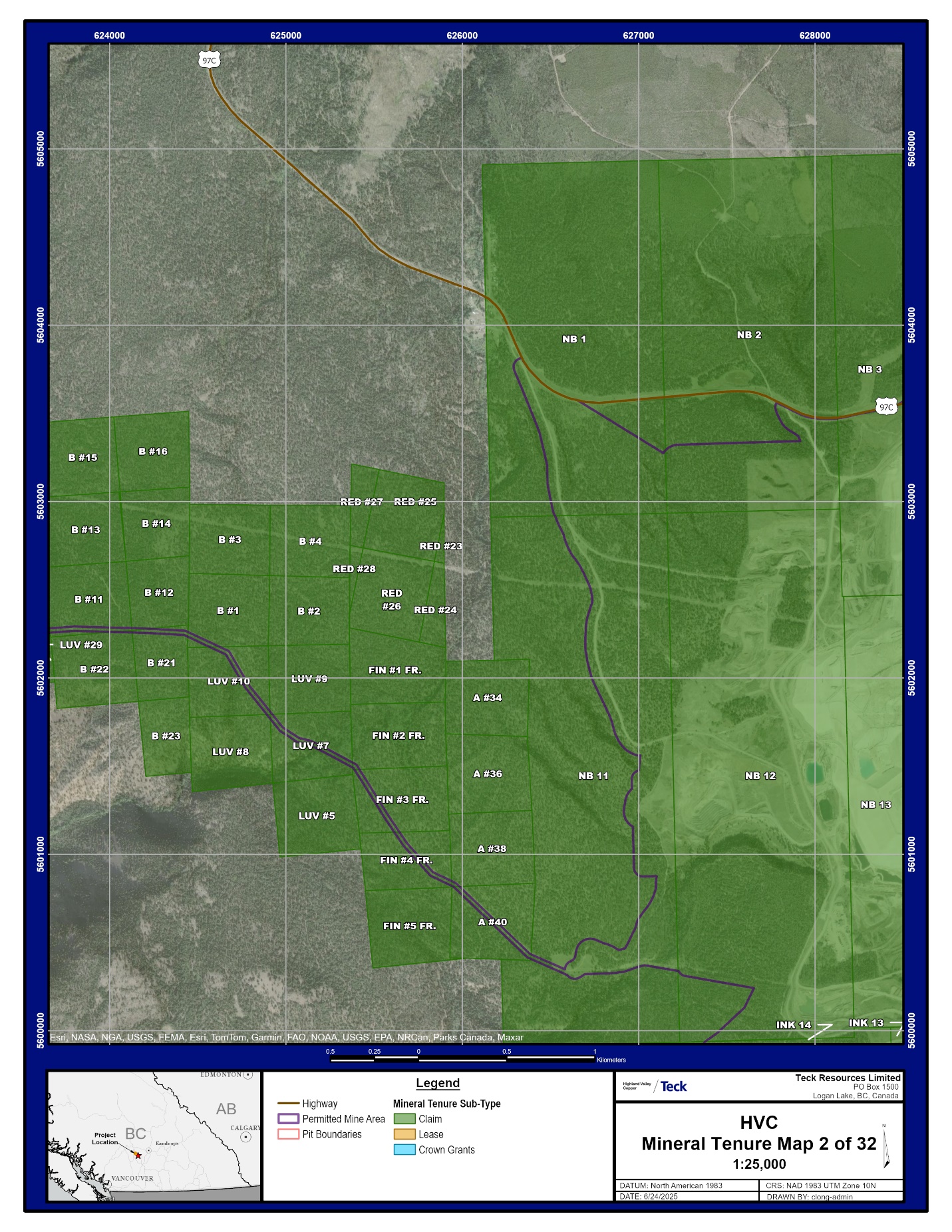
| October 2025 | Appendix A | |
|
NI 43-101 Technical Report on Highland Valley Copper Operations British Columbia |

| October 2025 | Appendix A | |
|
NI 43-101 Technical Report on Highland Valley Copper Operations British Columbia |

| October 2025 | Appendix A | |
|
NI 43-101 Technical Report on Highland Valley Copper Operations British Columbia |

| October 2025 | Appendix A | |
|
NI 43-101 Technical Report on Highland Valley Copper Operations British Columbia |
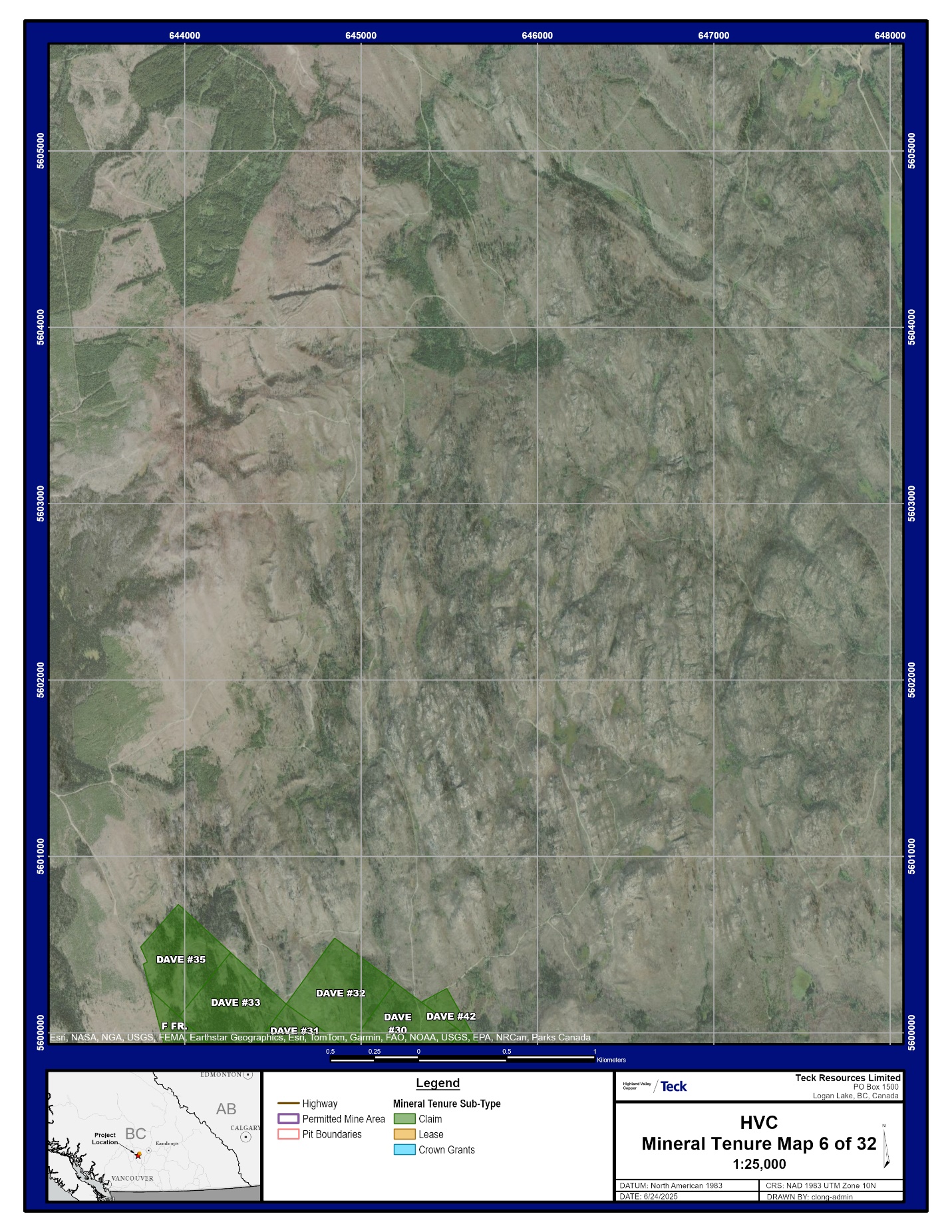
| October 2025 | Appendix A | |
|
NI 43-101 Technical Report on Highland Valley Copper Operations British Columbia |
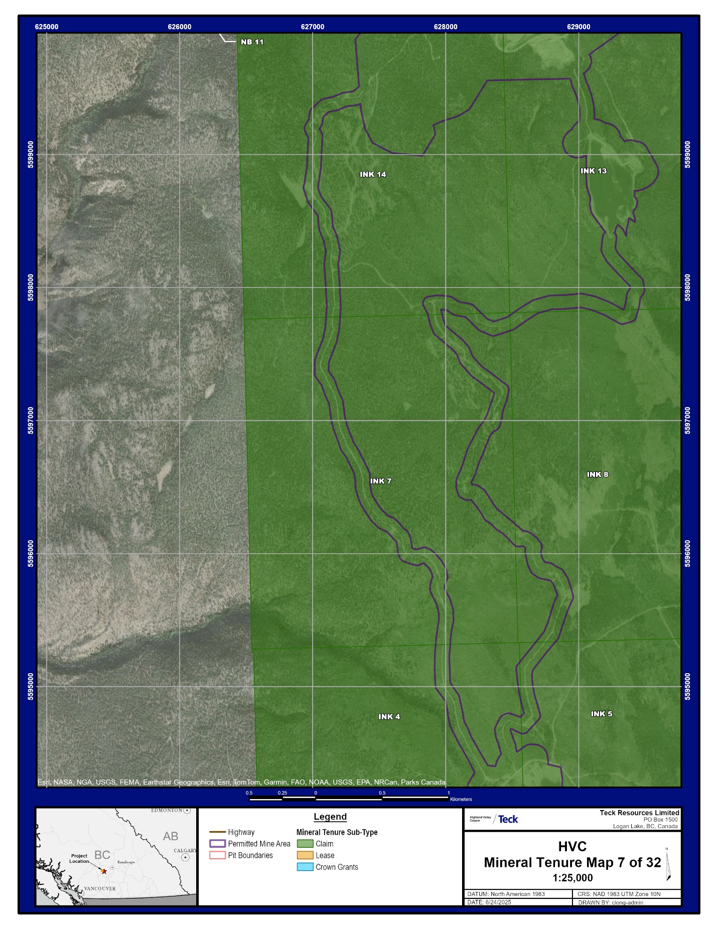
| October 2025 | Appendix A | |
|
NI 43-101 Technical Report on Highland Valley Copper Operations British Columbia |

| October 2025 | Appendix A | |
|
NI 43-101 Technical Report on Highland Valley Copper Operations British Columbia |

| October 2025 | Appendix A | |
|
NI 43-101 Technical Report on Highland Valley Copper Operations British Columbia |
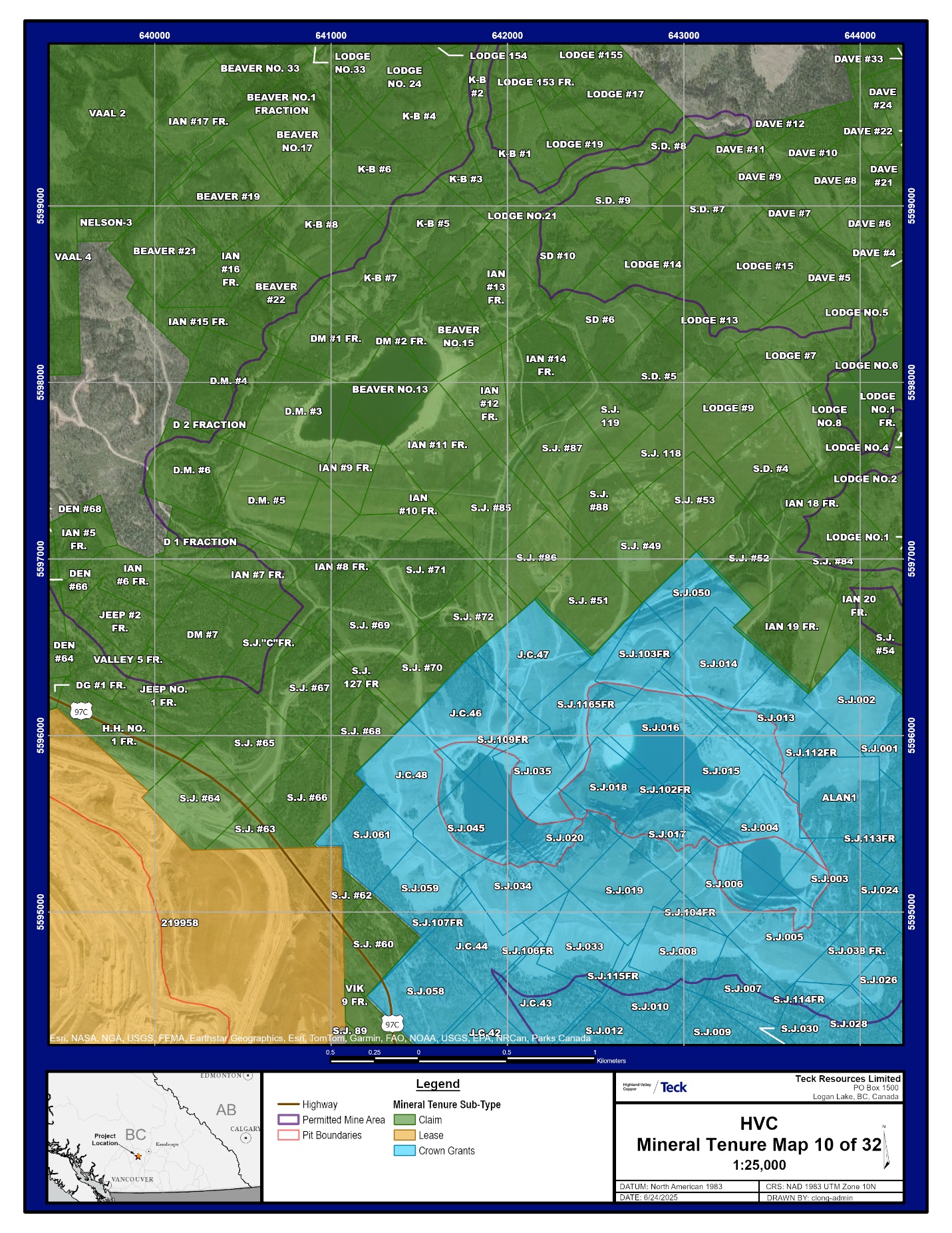
| October 2025 | Appendix A | |
|
NI 43-101 Technical Report on Highland Valley Copper Operations British Columbia |

| October 2025 | Appendix A | |
|
NI 43-101 Technical Report on Highland Valley Copper Operations British Columbia |

| October 2025 | Appendix A | |
|
NI 43-101 Technical Report on Highland Valley Copper Operations British Columbia |

| October 2025 | Appendix A | |
|
NI 43-101 Technical Report on Highland Valley Copper Operations British Columbia |
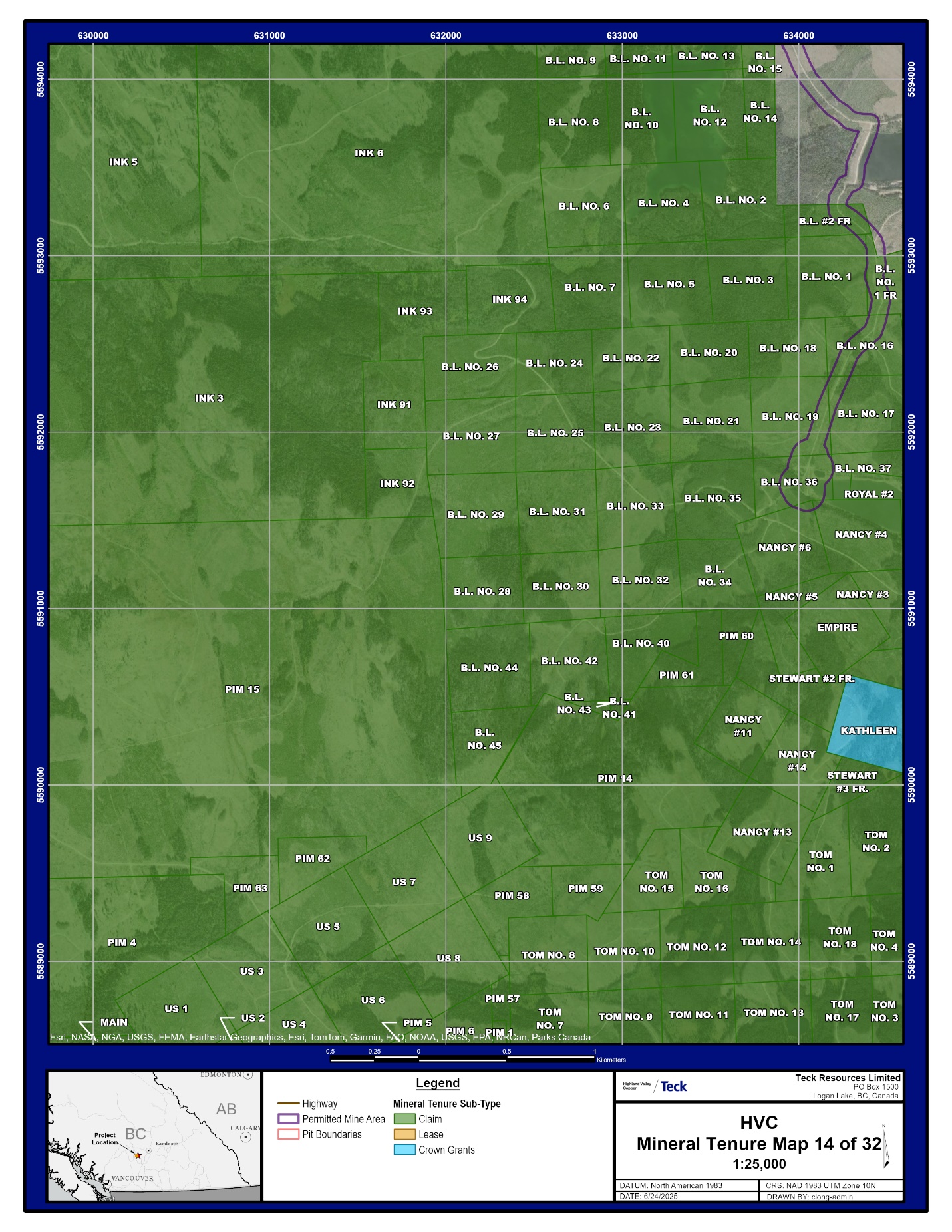
| October 2025 | Appendix A | |
|
NI 43-101 Technical Report on Highland Valley Copper Operations British Columbia |
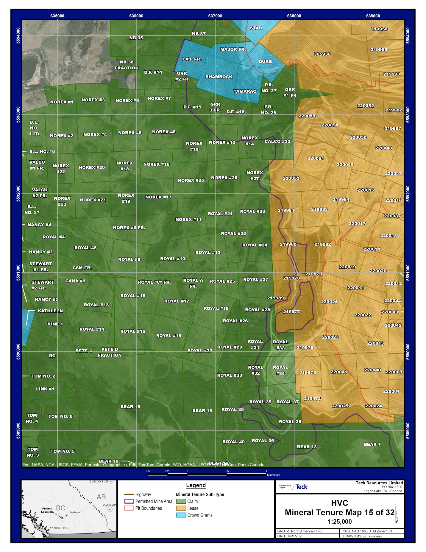
| October 2025 | Appendix A | |
|
NI 43-101 Technical Report on Highland Valley Copper Operations British Columbia |

| October 2025 | Appendix A | |
|
NI 43-101 Technical Report on Highland Valley Copper Operations British Columbia |
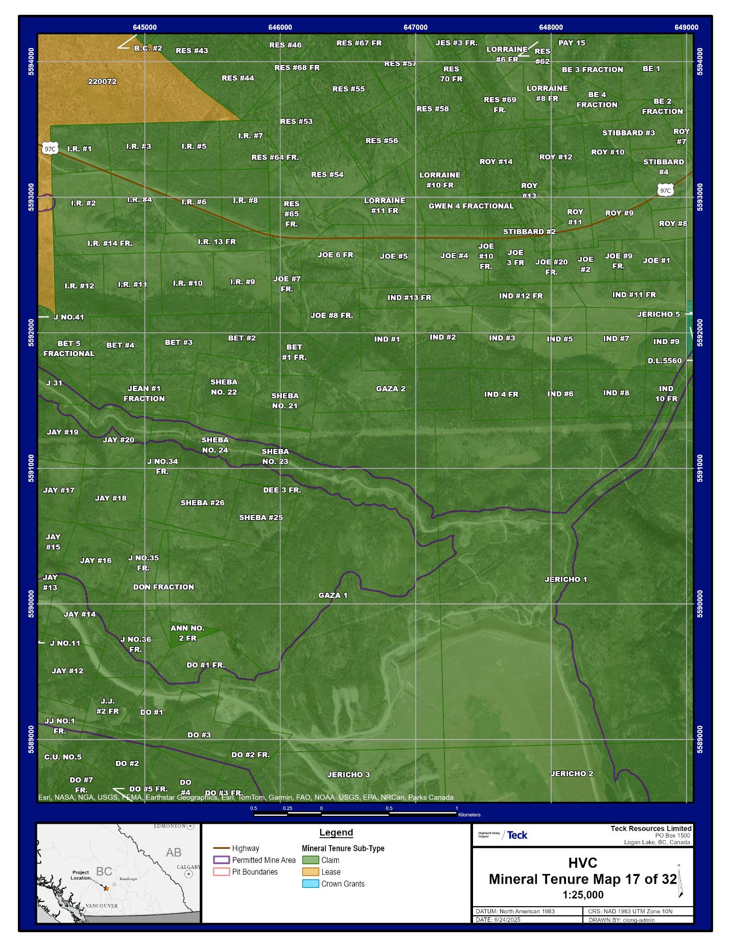
| October 2025 | Appendix A | |
|
NI 43-101 Technical Report on Highland Valley Copper Operations British Columbia |

| October 2025 | Appendix A | |
|
NI 43-101 Technical Report on Highland Valley Copper Operations British Columbia |

| October 2025 | Appendix A | |
|
NI 43-101 Technical Report on Highland Valley Copper Operations British Columbia |

| October 2025 | Appendix A | |
|
NI 43-101 Technical Report on Highland Valley Copper Operations British Columbia |
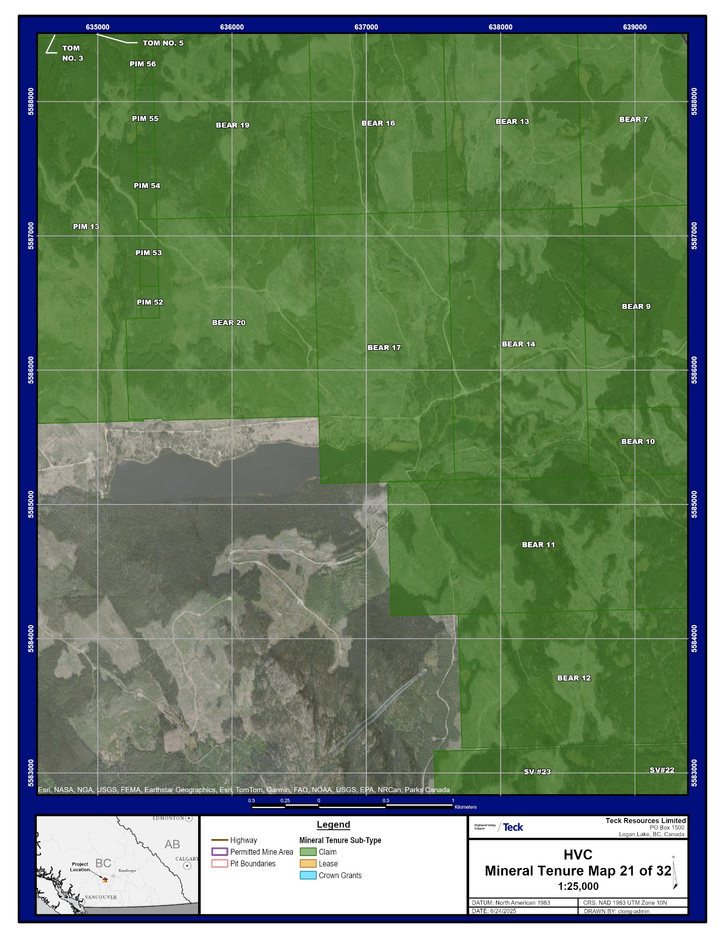
| October 2025 | Appendix A | |
|
NI 43-101 Technical Report on Highland Valley Copper Operations British Columbia |
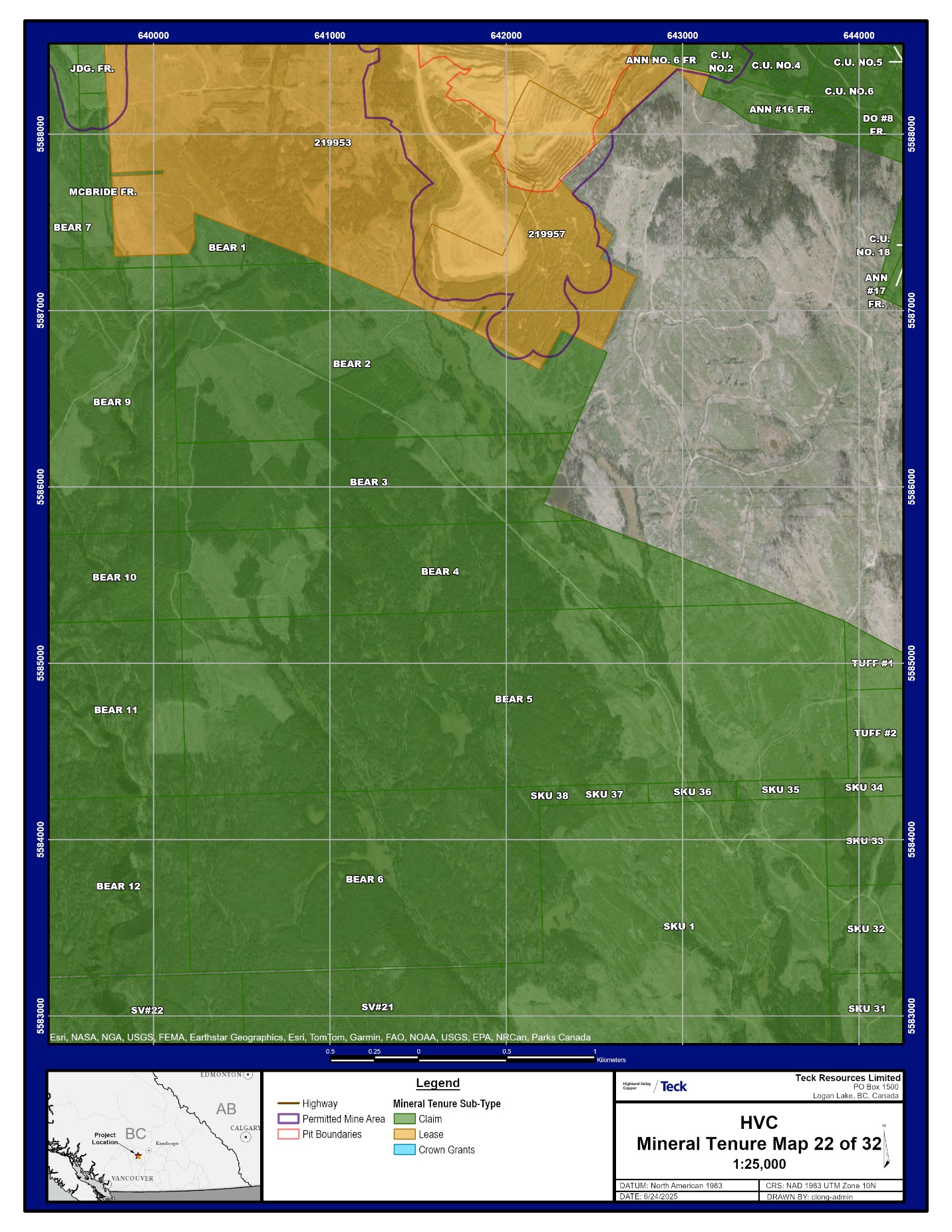
| October 2025 | Appendix A | |
|
NI 43-101 Technical Report on Highland Valley Copper Operations British Columbia |

| October 2025 | Appendix A | |
|
NI 43-101 Technical Report on Highland Valley Copper Operations British Columbia |

| October 2025 | Appendix A | |
|
NI 43-101 Technical Report on Highland Valley Copper Operations British Columbia |
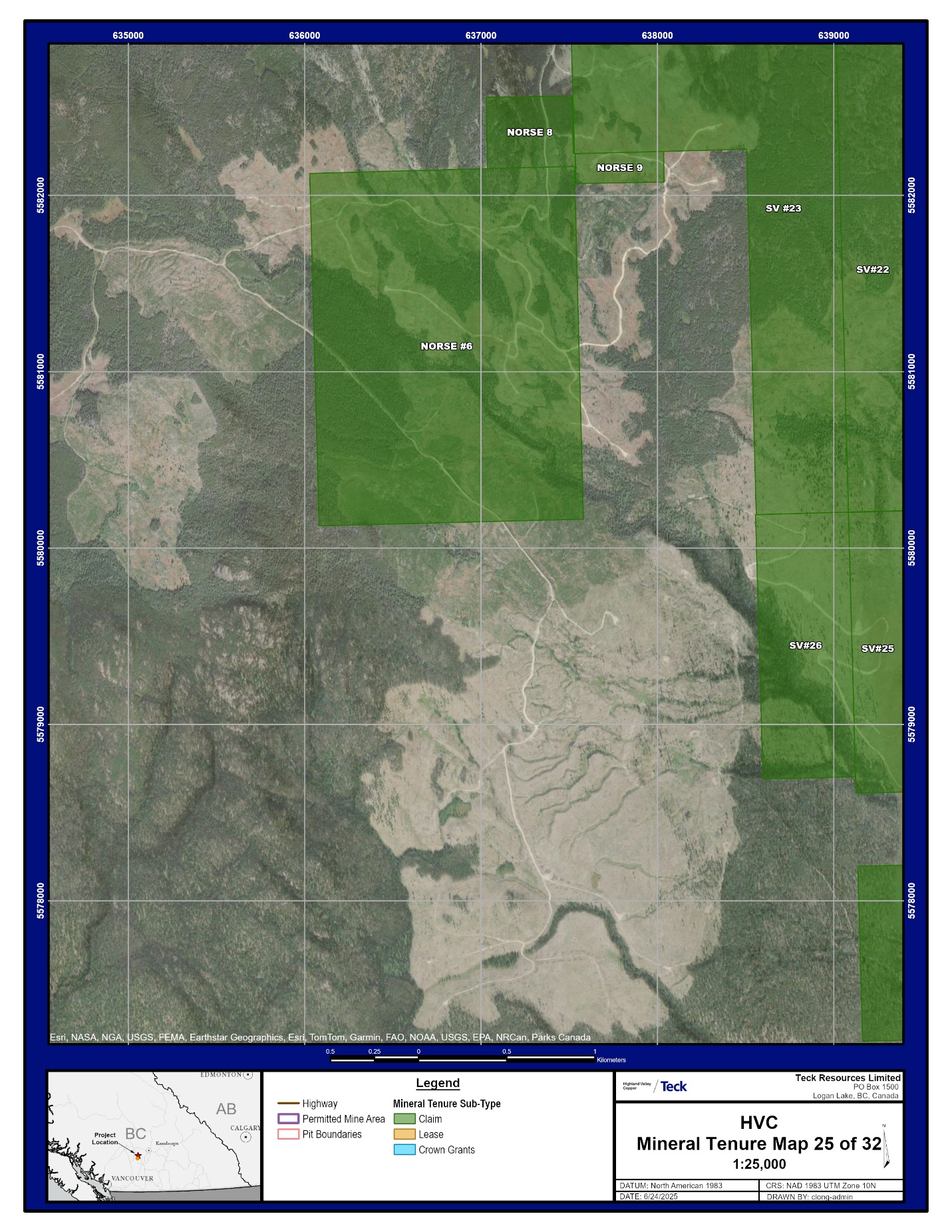
| October 2025 | Appendix A | |
|
NI 43-101 Technical Report on Highland Valley Copper Operations British Columbia |

| October 2025 | Appendix A | |
|
NI 43-101 Technical Report on Highland Valley Copper Operations British Columbia |
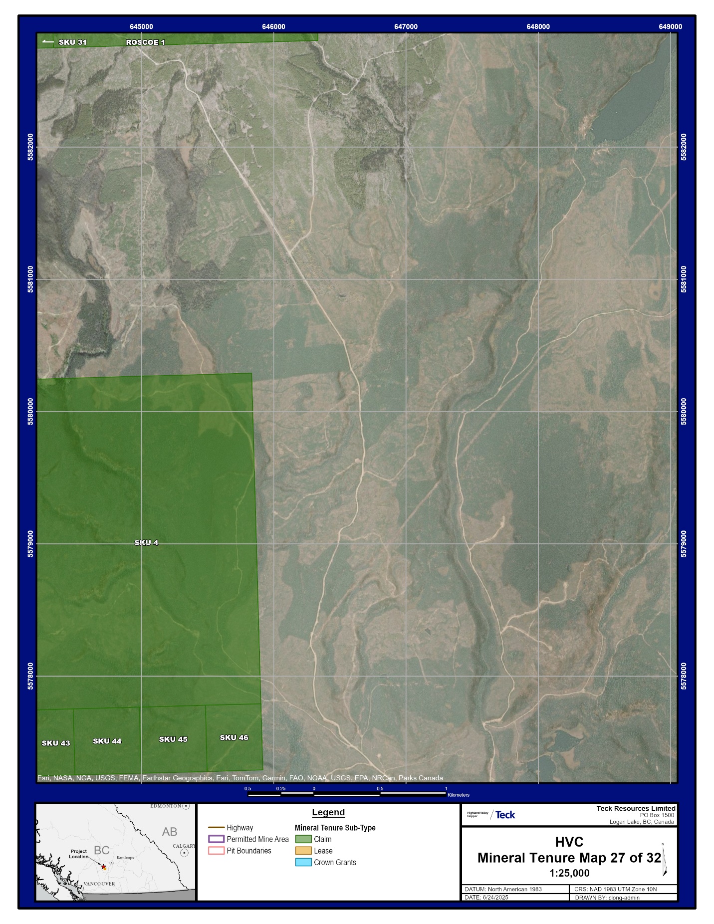
| October 2025 | Appendix A | |
|
NI 43-101 Technical Report on Highland Valley Copper Operations British Columbia |

| October 2025 | Appendix A | |
|
NI 43-101 Technical Report on Highland Valley Copper Operations British Columbia |

| October 2025 | Appendix A | |
|
NI 43-101 Technical Report on Highland Valley Copper Operations British Columbia |

| October 2025 | Appendix A | |
|
NI 43-101 Technical Report on Highland Valley Copper Operations British Columbia |
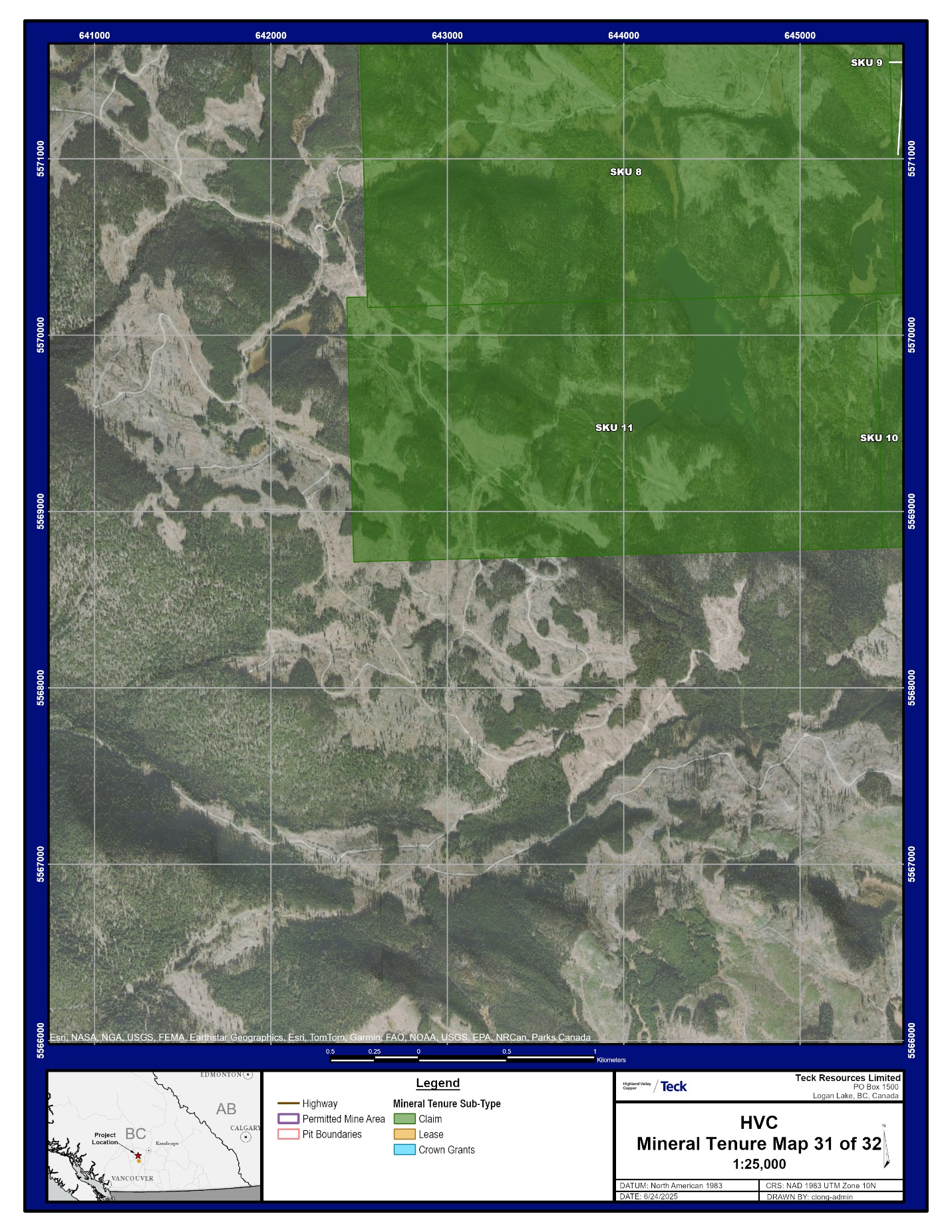
| October 2025 | Appendix A | |
|
NI 43-101 Technical Report on Highland Valley Copper Operations British Columbia |

| October 2025 | Appendix A | |